Perhaps this was not stated clearly enough previously but this is the same keyboard as in the MNT Reform laptop, in a different case for desktop use.
You need to read the documentation closely and start disassembling things. Everything will make a lot more sense once you do. There’s a switch labeled “Standalone” on the PCB of the keyboard, but unless you take the case off you will not see it—the PDF of the keyboard manual I sent you states this. Please trust us we know these computers pretty well
You have just about everything you need to make this work. If you get stuck we’d be happy to answer other questions.
I’ve certainly learned a ton about this stuff by giving it a shot Just be sure to remove the batteries and unplug your Reform before doing anything and you’ll be fine.
Very much appreciated information. Here is where things stand now:
I have downloaded the keyboard.hex file matching the v3 keyboard with the US-QWERTY format. The instructions tell me to run a shell script called flash.sh – unfortunately this script is tied heavily into the Linux world of which I am not a part :small:grin: I do however have the keyboard plugged into a USB port and I think I have enough information to run the programmer “dfu-programmer”.
According to the man page the dfu-programmer needs a target and a command. The target in my case is atmega32u4:0:3 and the commands are “erase”, then “flash” then “start” as three invocations of the programmer.
I do not have the “udevadm” command so I am unable to issue the “udevadm wait” command that follows those three programmer commands. What i would like to know and have someone tell me if this approach (three programmer invocations, and then wait for a while) is acceptable. If so, then I don’t need to run the “flash.sh” script.
I understand that all this is done as user “root” and that I have to put the keyboard in programming mode (CIRCLE-X) first.
Once I get confirmation on this approach, then I have to remove the keyboard from the standalone case it arrived in, and install it into the laptop as a replacement for the older keyboard that came with the DIY kit.
Thank you for this! I now have my marching orders to work with tomorrow. One thing I don’t understand is why it is that I need to be flashing the keyboard (either the one that came with the DIY kti or the new one “v3” which arrived this week).
They both look like decent devices, and one could quibble with some of the keycaps and key placements, but not enough to be show stoppers.
Since I don’t plan to do anything “fancy” with the programming of the v3 keyboard, I have to assume the flashing is to place the US-QWERTY format onto the device. Yet I was certain I read on the Crowd Supply product blurb that this keyboard already was a US-QWERTY format.
That said, wish me luck, because after flashing and installing the new keyboard as a replacement for the older style I have tn the DIY kit, if the laptop fails to boot, I will be back here with more questions and seeking more wisdom from you folks!
The reason you need to program the keyboard is that the same device can act as a standalone OR laptop keyboard, but you need to flash a different firmware for each use.
The keyboard you purchased is a standalone QWERTY-US keyboard, so it needs to be flashed with the firmware for a laptop QWERTY-US keyboard. Hopefully you downloaded the right firmware (hex file)
Note that there is a single source code for the firmware (where you found flash.sh), but there are compile time flags that indicate which kind of keyboard you have to generate the right hex file.
When you do install the keyboard in the laptop you will also need to flip a switch that (as explained above) will be visible once you remove the case.
Thank you for that very clear explanation of the reason for flashing of the keyboard. It occurred to me that the presence of that slide switch could have been used to select between a standalone set of firmware and a laptop set of firmware. The fact that this is not the case my be because there isn’t enough flashable storage on the ATmega32u4 CPU chip.
The error is: “Unsupported target ‘atmega32u4:0,3’.”
Looking at the file arguments.c in the source of dfu-programmer there is a function called “assign_target” around line 400. The code in this function checks for the colon character in the “target” parameter and parses the “usb-bus” and the “usb-addr”. If either of these two numbers is less than OR EQUAL to zero, the function returns an error (-1 in this case).
I don’t know how to get anything other than zero,three from the output of the lsusb(8) command: Device /dev/ugen0.3
I hope I am missing something, but at this point I am unable to run the dfu-programmer command without getting that error.
FINALLY! I realized that I had more than one USB connector so instead of using the one on the front of the case (that gave me atmega32u4:0,3) I found another USB connector in the rear of the case that gave me a different usb-bus and usb-addr.
This time “dfu-programmer atmega32u4:1,2 erase” worked!!!
The other two “dfu-programmer” commands also succeeded!
I thank you all for you help. Now, to install the v3 keyboard into the DIY kit as a laptop US-QWERTY keyboard and see if I can get the laptop to turn on and run. Wish me luck!
I swapped the old keyboard out and the new v3 keyboard into the DIY kit
and plugged in the power brick which I then plugged into wall AC power.
All that happened was a red LED began to shine on the underside of the laptop. I then pressed the CIRCLE key and the OLED display lit up in the correct format. So far do good.
BTW, I did move the slide switch on the v3 keyboard prior to installation.
Using the up and down arrow keys on the keyboard I can move up and down the OLDE menu. Again, so far so good. However the keyboard does not light up (or down) as I press the F1 and F2 keys. This is not good.
Pressing the “b” key I can see the battery status. All eight batterys are responding at about 3.5 volts. There is an “off” and “on” status to the right of the battery readings. This status corresponds to whether I press the 1 (one) or the 0 (zero) keys in vain to try to turn the laptop on.
I have spent a lot of money, and wasted a lot of time and effort, and I am still left with a dead laptop.
If anyone wants to make a suggestion here, I am open to any help.
Depending on your motherboard revision, you should also see a pair of orange LEDs which indicate that you have power and that it’s used to charge the batteries.
In my unit there are three red LEDs but they are on my A311D board.
There is also a pair of white LEDs labeled 3V3 and 5V which are constantly on for me with motherboard 2.5.
If instead of using F1 and F2, what happens if you select the desired entry with up/down and then press enter?
This is actually already very good. Below the on/off, you see a reading in Ampere. It shows you whether your batteries are currently getting discharged (positive values) or charged (negative value). If you wait long enough for the batteries to balance themselves, than above the on/off reading in the battery status menu you should be getting what probably right now says “???” to turn into “100%”. What does it say in your case?
The fact that you can read the battery value means that your keyboard can successfully communicate with the motherboard. This is great. I can think of a few next steps. What CPU module did you install? Do you have an SD-card with a corresponding system image inserted when you select “Power On” in the OLED menu?
Do you happen to have a USB UART adapter around that you could use to see what happens on the serial output when you press “Power On”?
When you press circle and then 1 to turn the computer on, you should see the MNT logo on the keyboard OLED, and after a few seconds stuff would show up on the screen.
The screen remains black if you don’t have the right system image in the SD card, or if the SD card is not properly clicked in (I have bumped and unclicked the SD card in the past and wondered why my reform wouldn’t boot!).
When I plug in the power brick, the only thing I see on the reverse is the single red LED. When I then press CIRCLE-1, two white LEDs light up.
The OLED display reads as follows:
all eight batteries at 3.5
on the right, from top to bottom: ??? then On, then -1.43, then 28.52
Using the ENTER key after selecting F1 or F2 does nothing – the keyboard backlights do not seem to be functioning. Interestingly, when I had this same v3 keyboard plugged into a USB port before installing it into the laptop, I could use the F1 and F2 keys to control the backlighting.
At the same time (yesterday) that I swapped the keyboards, I installed an SSD card, so I would have to remove the back plastic cover AND the SSD to be able to read the motheboard revision. Is this important to get this laptop into working staus?
I did not “install a CPU module” – I simply followed the 23 steps that came with the DIY kit showing how to put everything together. I don’t even know what you mean by “CPU module”. There was a motherboard and a keyboard and a bunch of cables. There also was an SD card that I plugged in prior to my first attempt to boot the laptop. It came with the DIY kit, but I don’t know anything about it.
I do not have a USB UART adapter – I don’t even know what that is.
When you say “serial output” what do you mean? Where is the serial output found or located?
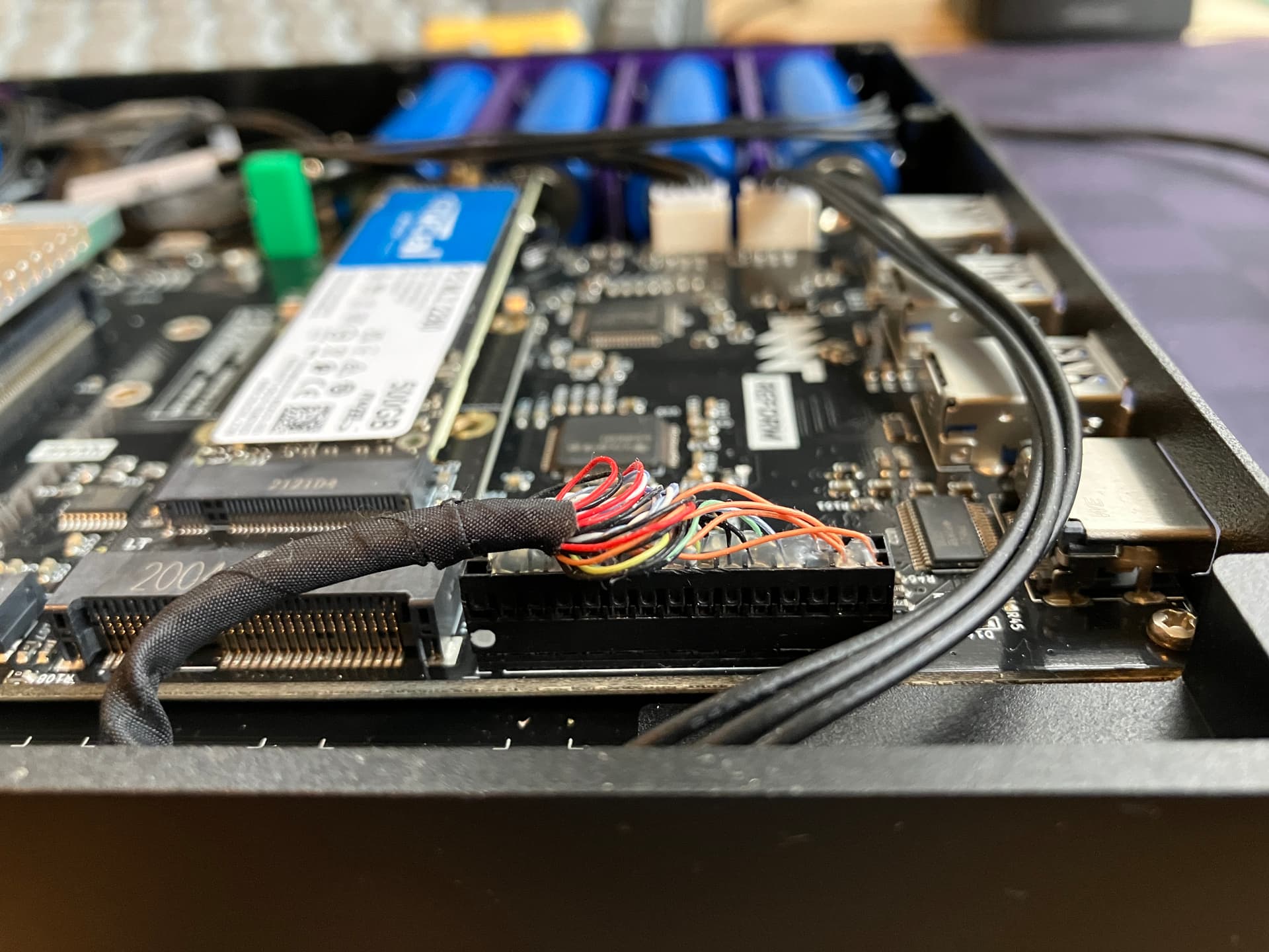
Can you show us a photo of your mainboard from the bottom? That is, the side that has the SSD on it? You do not have to take off the transparent plastic cover for that, just make sure that there is no reflection.
When I press the CIRCLE-1 keys the OLED does light up with the proper menu as I now understand. I do first see the MNT logo which disappears and then the menu appears. At no point after this does anything show up on the screen. This may be a self inflicted problem since I was not certain which way to install the display cable (from step three of the printed instruction assembly sheet). There is a white dot on the header which indicates pin one on the connector, but there is no corresponding visible indication on the motherboard slik screen. So I have a 50:50 chance that the display cable is plugged in the wrong way.
Step three says the white dot should “point in the direction of the display” but at this point the laptop is inverted and I wasn’t even sure what or where the “display” was, or if it was something I had yet to install.
BTW, the laptop has been “charging” for several hours now, and the OLED display now reads 100% where before it was just “???”.
I had the SD card properly seated when I first tried powering on with the STANDALONE keyboard at that time. Plus how do I tell if I have the correct system image on that SD card?
In the link you gave about properly flashing the system image, there is a table where the first (left hand) column has the heading: “PROCESSOR MODULE”. How do I determine which processor module I have? And, what is the processor modulle? Is it the motherboard? And just where is the processor module located?
Ok, to be 100% sure here is a picture of the display connector on my reform. You can see where the white dot is.
The processor module is under the heatsink in your motherboard. The module is connected to the motherboard in a couple of places including a ribbon cable that carries the display signal from the module to the motherboard. You could unscrew the heatsink and check that the module is seated correctly and the ribbon cable is plugged in properly. I am 99% sure the DIY kits from crowdsupply all came with the NXP i.MX8MQ module, with a black heatsink.
About the SD card I was just thinking in case it was not flashed correctly in factory, that could be a problem leading to nothing showing up on the display. As could the display connector being reversed, or the ribbon cable between the CPU module and the motherboard not being connected, etc.
The processor module has among other things the CPU and memory, display and ethernet controller, etc.
Since the DIY kits in crowdsupply came with a relatively old system image, I would suggest flashing a new image to the SD card anyway.
Although one can use apt upgrade normally now, I think the image from those kits would be the same one shipped with the first batch from crowdsupply (and before a lot of refactoring done by @josh etc) and I assume there would be some hiccups along the way.
BTW after the computer is working you may want to flash the system controller with new firmware as well. The new system controller firmware may be required for the linux kernel to get battery status and to use less power while off (and perhaps other features as well).
(Sorry for adding to the list, but I thought I would warn you that the system controller firmware in those older DIY kits would not have all features but that can be updated)
I did indeed have the display connector installed incorrectly. As long as I was going to open the back cover to check on the firmware badge which was hidden under the SSD, I decided to reverse the display connector at the same time as I unscrewed the SSD module. BTW the firmware badge revealed that I am using the older MREFPMOB20R02 firmware dated from 2020-10-29. Then I reinstalled the SSD module and turned over the laptop. Upon pressing the CIRCLE-1 keys I waited patiently as the OLED screen displayed the MNT logo and then blanked out. I was completely shocked to see the screen display some lines as the system booted.
The font is way too small to have read all these lines and they scrolled off the screen all too fast for me to follow, but finally it stopped with the login prompt. I logged in as root and created an account for myself and then I finished with “shutdown now” as root.
I have a lot to learn, and perhaps someone here can point me to some useful tutorial material. But I have made significant progress today and I am thrilled to have finally gotten the durn thing to work correctly.
Thanks for the photo of the display connector. I had a 50:50 chance that it was installed incorrectly. I lost that bet as you can tell from my recent post. The one thing I don’t have that I would like to have is proper key backlighting. What do I have to do to get the F1 and F2 keys to work?
That is great news it works now!
You can try circle-F1 or circle-F2 to control the backlight directly with the keyboard (or use circle and follow the keyboard OLED menu).
And definitely read the manual as there is tons of useful information including for new linux users.
Thanks. Interestingly enough, I turned on the laptop for the second time after it worked the first time. It had been sitting, unused, for perhaps an hour or so. Upon power up, the entire keyboard lit up like an explosion! Then the screen (which had started to scroll) went blank and I wondered what the heck was going on! After a short wait, the screen continued onto the login: prompt, AND THE KEYBOARD NOW RESPONDS TO THE F1 and F2 keys!!! I swear I did nothing but “shutdown now” and then after waiting while posting here, pressed the CIRCLE-1 keys and now everything seems to be working – I don’t understand, I really don’t…
Can you point me (URL) to the “manual”? Also, how do I determine the boot up sequence? Usually there is a BIOS in a computer where one can alter the order of devices/interfaces/drives from which to boot off. The SD card contains the O/S as I understand it. If I tried to turn on the laptop with the SD card removed, would anything happen? If I wanted to boot off a different (say, USB based) media, would the SD card remain, or would that cause a conflict?