[Original thread title: Current status of Reform keyboard PCB(s)?]
I guess these are questions for @minute, but I figured I’d ask here in case others are interested or know the answers…
I’m looking into building a custom keyboard for my Reform, and I noticed there’s now a reform2-keyboard3-pcb source dir, and some recent social media posts about the v3 keyboard [1][2][3][4][5].
I’m trying to figure out if I should base my design on the original reform2-keyboard-pcb project, or the new reform2-keyboard3-pcb. (Traditional stagger is one of the changes I want. I also don’t care (at least to start with) if there are gaps at the sides from not having 1.75U keycaps, etc.)
Is the keyboard3 design stable and suitable for getting fabbed, or is there still more work to be done? I see the commit message says “initial design”, and that the files have the traditional stagger and holes for the 2U stabilizer - but not the “standalone vs laptop switch” mentioned on mastodon. Is there a later version than what’s in the gitlab - and if so, can it be made available? I’d rather not go to the effort of modifying a design which is going to get other improvements soon…
I also notice that it’s still using the ATMEGA32U4-AU - which are thankfully back in stock. But the Pocket Reform’s keyboard is using RP2040 (and the Reform trackball module also got converted to RP2040). Are there any plans for reform2-keyboard3 to use RP2040 in the near future? I’m fine if not, but in that case I’ll order some ATMegas soon (to avoid any possibility of them going out of stock again).
The most important parts of a custom reform keyboard are the physical size, and the connectors. So long as you match those (and on all the alternative keyboards you mentioned I imagine they’re exactly the same), it’s just a matter of writing keyboard firmware that plays nicely with the system controller.
That said, I’m not sure if there exists any firmware yet for non-atmega based keyboard? I didn’t see any in the reform repo from a quick glance, so maybe minute is still working on it.
It’s the Pocket Reform which is using the RP2040 (pcb and fw). I don’t think it directly translates to the Reform, since the keyboard layout is different, it’s a merged keyboard/trackball, and has RGB LEDs. My guess is that eventually the Reform’s keyboard will get converted to RP2040, but there’s no longer any urgency since the ATMegas are available again.
In terms of the reform2-keyboard-pcb vs reform2-keyboard3-pcb dirs, after figuring out how to have multiple copies of KiCad open, I visually compared their schematics and PCBs, and was able to confirm that (currently at least) the only difference is to accommodate the adjusted key layout. I assume this means that any further changes (eg. switch for standalone vs laptop) haven’t been uploaded because they’re not ready yet.
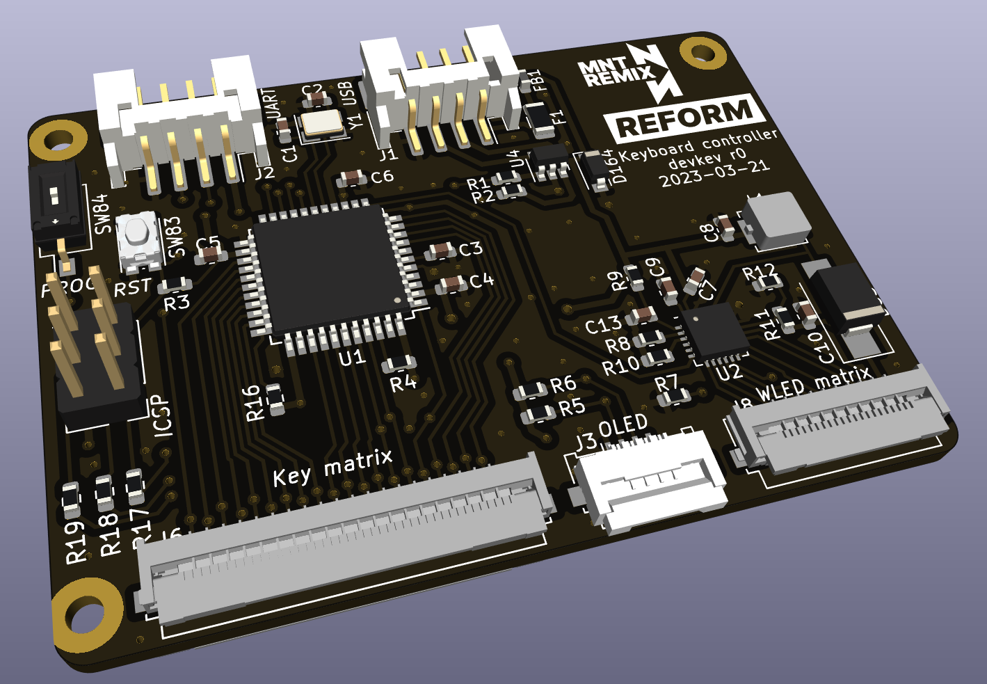
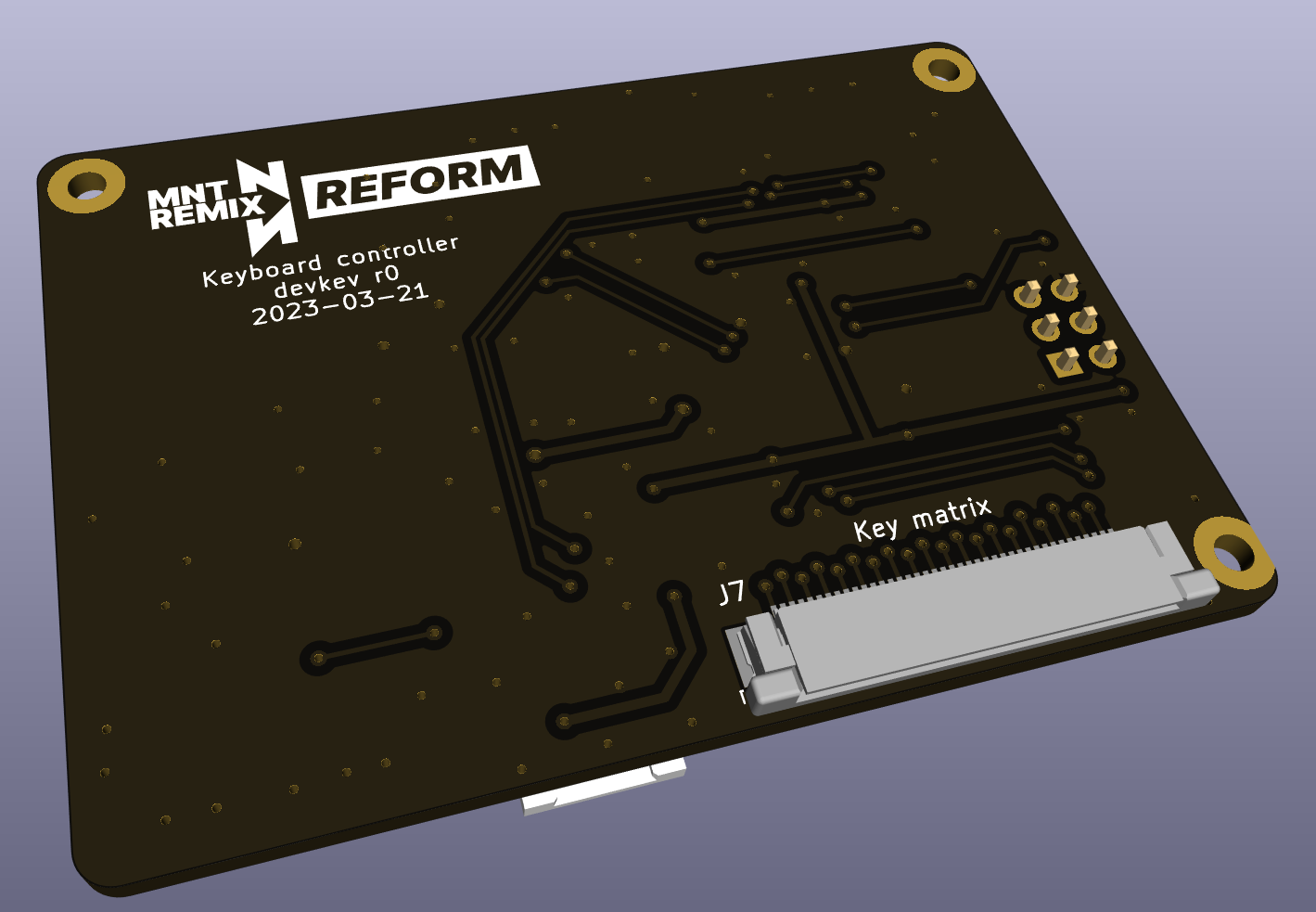
My plan is definitely “just” to rearrange the physical layout, reusing the original firmware (ISTR people having difficulties hacking QMK etc to talk to the LPC/OLED, and have the reform-specific menu). That said, I’m trying a pretty ambitious “rearrangement” - the MCU and other stuff will be on a small separate board (in the empty space above the SD card slot), that’s connected by FFC to the matrix of switches on the “actual keyboard”. The hope is that this will make it easier for me (and others) to quickly and easily try out various alternative keyboard layouts - since you only have to worry about making a simple board that connects the keys to the FFC connector, while the controller board stays the same (perhaps reflashed for adjusted col/row pin assignments). I’ve designed an initial version of the controller PCB (literally by removing the switch matrix and then rearranging what remained) and now waiting for it to be made.
I’m a little concerned about RFI from the FFC - especially the powered PWM WLED lines (but for now I can just ignore and not connect the WLED FFC, if necessary). Anyway, my next steps are to order parts, and design one (or maybe more?!) “matrix” layout PCBs (by taking the MCU etc off the OG board) and get them made too.
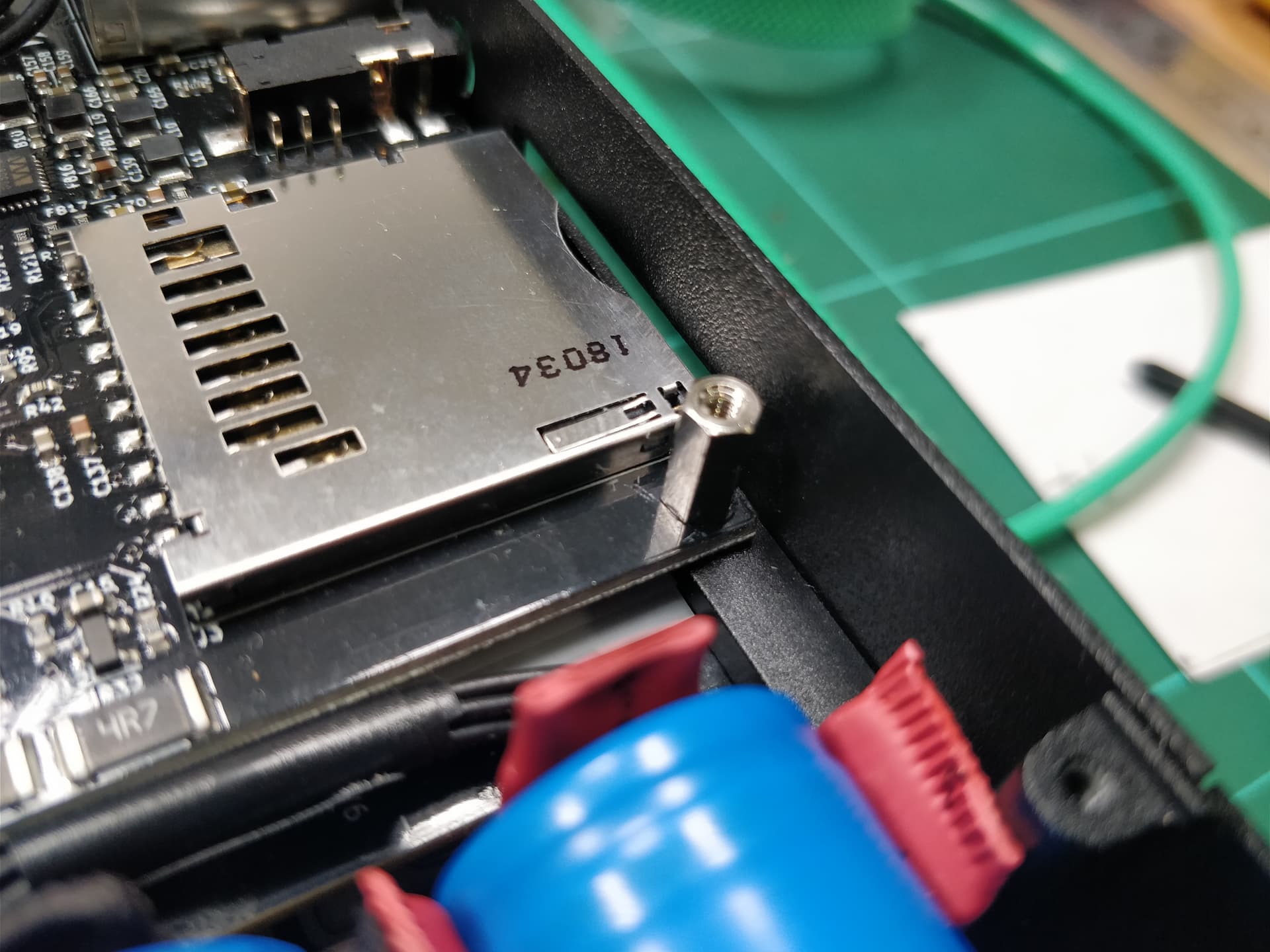
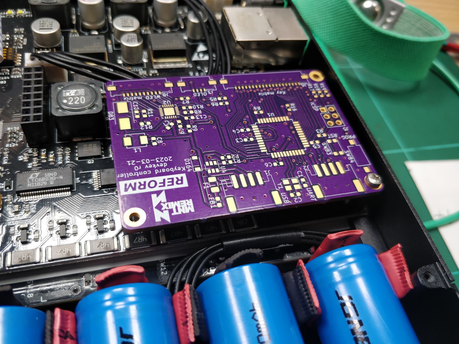
Sorry for the delay updating. The controller board and parts have arrived, and I’m trying to find time to assemble it. (Hand-soldering all the tiny 0603 passives seems daunting!) It fits very nicely in the expected space, and I think mounting it with a single standoff for the bottom-right motherboard screw will work fine.
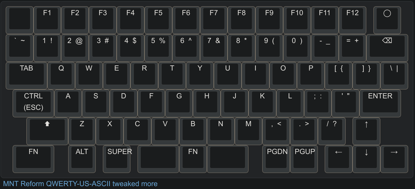
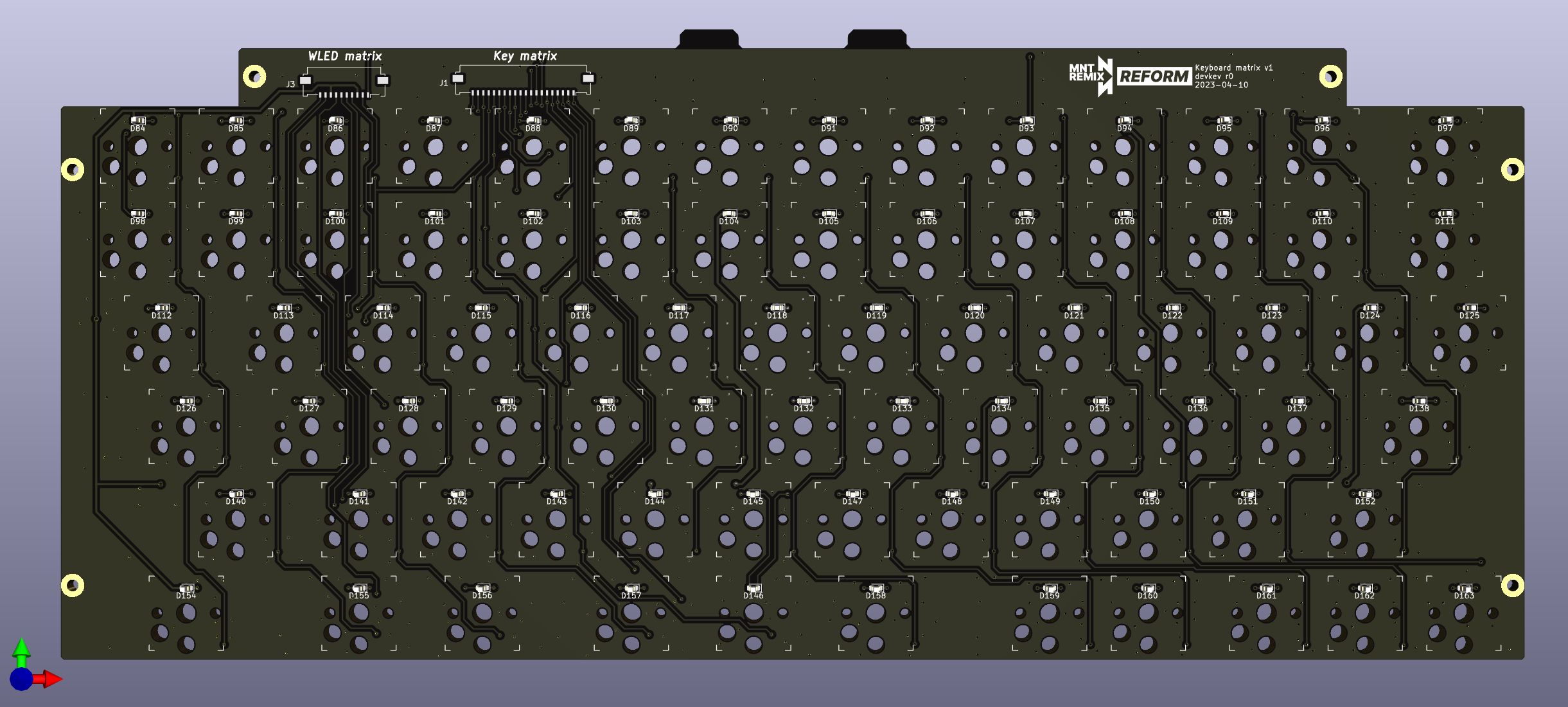
The matrix board re-design was more fiddly - and so took longer - than I had expected, but has now finally been finished and sent for production! The main change is to use this layout:
Which has traditional stagger, but still uses only 1u and 1.5u keycaps. It also moved the thumb keys (space and the various modifiers) to where I think my thumbs naturally sit on all the other keyboards I use.
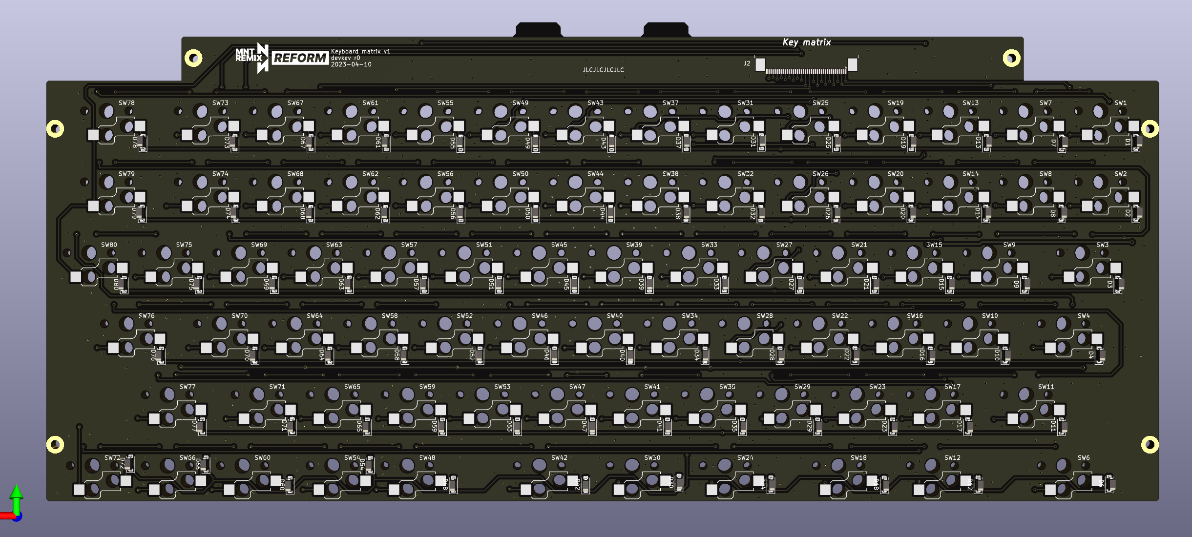
The other main change is to use Kailh Choc 1350 hot-swap sockets, rather than soldering the Choc keycaps directly in. These sockets are significantly cheaper than the actual switches (especially the Choc Sunsets that I hope to eventually use), which is better for prototyping layouts. (In bulk (few hundred+), the sockets are ~0.10 USD or less, compared to ~0.50 USD or more for switches.) This had numerous flow on effects:
They’re surface mount on the bottom, rather than thru-hole (automatic vias), which affected routing a bit.
They poke out beyond the regular switch footprint, especially on the left (when viewed from the front). This meant that the pad for the top-left key’s socket overlapped with the nearby mounting hole. I had to shift the entire layout over 2mm to fix this. Hopefully it won’t be very noticable. It does mean that the original keyboard bezel now has no chance of working, but with my layout it would already have several holes anyway. I’ll prototype a bezel for this layout out of modeller’s cardboard, and probably eventually get a new custom bezel made.
Shifting everything right by 2mm made the bottom right key switch itself get in the way of the mounting screw in that corner. I dealt with this by shifting the arrow-cluster keys left by 1mm, so the gap to them is now slightly less than 0.25u as a result (3.65mm instead of 4.65mm). Hopefully this also isn’t very noticable.
The hot-swap sockets require larger holes, and in the bottom row this caused the holes to intersect with the bottom edge of the board. I made the board larger at the bottom by 1mm, which gives (just) enough clearance for the holes (and socket itself), while also looking like it’ll fit in the chassis without touching the battery boards.
Other changes included:
I switched the diodes from the tiny SOD-323 (actually the pads were 0603) to slightly larger SOD-123, which will hopefully be slightly easier to hand solder (and the diodes were also slightly cheaper).
When removing the USB-C socket, I realised that the PCB notch it’s on could be used to stablise the top edge of the keyboard, which flexes ever so slightly under pressure. I couldn’t move it to the middle, because the chassis has a protrusion there, so instead I put one on either side of it.
@mtm, are you interested in looking at or using the Kicad sources now, even though I haven’t yet gotten to the stage of trying to actually use them (ie. discovering any of my mistakes)? I was going to wait until after assembling and testing the controller board, but if you’re keen then I could publish them sooner instead.
I just wanted to post a quick update to say that, after many many hours of painstaking soldering, the initial versions of these boards are done. Although there are a few small issues, overall they work quite well and I’m very happy with the result! I’ll be able to post photos, details, and sources next week.