I had some strange Wi-Fi issues on my own RK3588 Pocket Reform with the AsiaRF Wi-Fi card and a single laird/ezurio antenna. The antenna was in the original location on the headphone/switch port board.
Wi-Fi would reproducibly stop whenever i played a YouTube video fullscreen, but resume when i went out of fullscreen. I then did some focused experiments with always-on-top terminal windows obscuring part of the video, and that helped.
My theory is that fullscreen video creates enough EMI on the display flex cable that it interferes with the antenna close to it (even if the display and antenna cables don’t touch—as we’ve already established, that’s a problem).
I moved the antenna now to the other side of the device (sticked on the back of the lid, in the corner near ethernet, with ample distance to the lid edges and the edge of the lid’scopper coating), and the issue is completely gone. I only tested this in my small home apartment with pretty powerful Wi-Fi cable router so far, not outside.
BTW, one antenna can potentially work better than double antennas (because they can interfere with each other if close), but YMMV. Still looking for the best possible combination.
I’ve been using the RK3588 pocket for a few weeks and noticed that occasionally the Wi-Fi would cut out for a few seconds, but fullscreen video didn’t reproduce it on my unit.
I just tried your recommendation and so far it seems to have resolved the issue!
That’s good to know.
I have my (two) antennas mounted on the outside, ontop of the lid, and the wifi performance has been consistently good. But I’d like to put the antennas back inside.
I wonder if we could embed an antenna in the top lid as a copper layer with a surface mount connection on the inside. That would be a neat solution and also “cheap” since the lid is already a PCB.
No sorry, I’ll screw around with goetic inscriptions and archetypical divination systems but antenna design is real occult sigil magick. Needs grown-up supervision
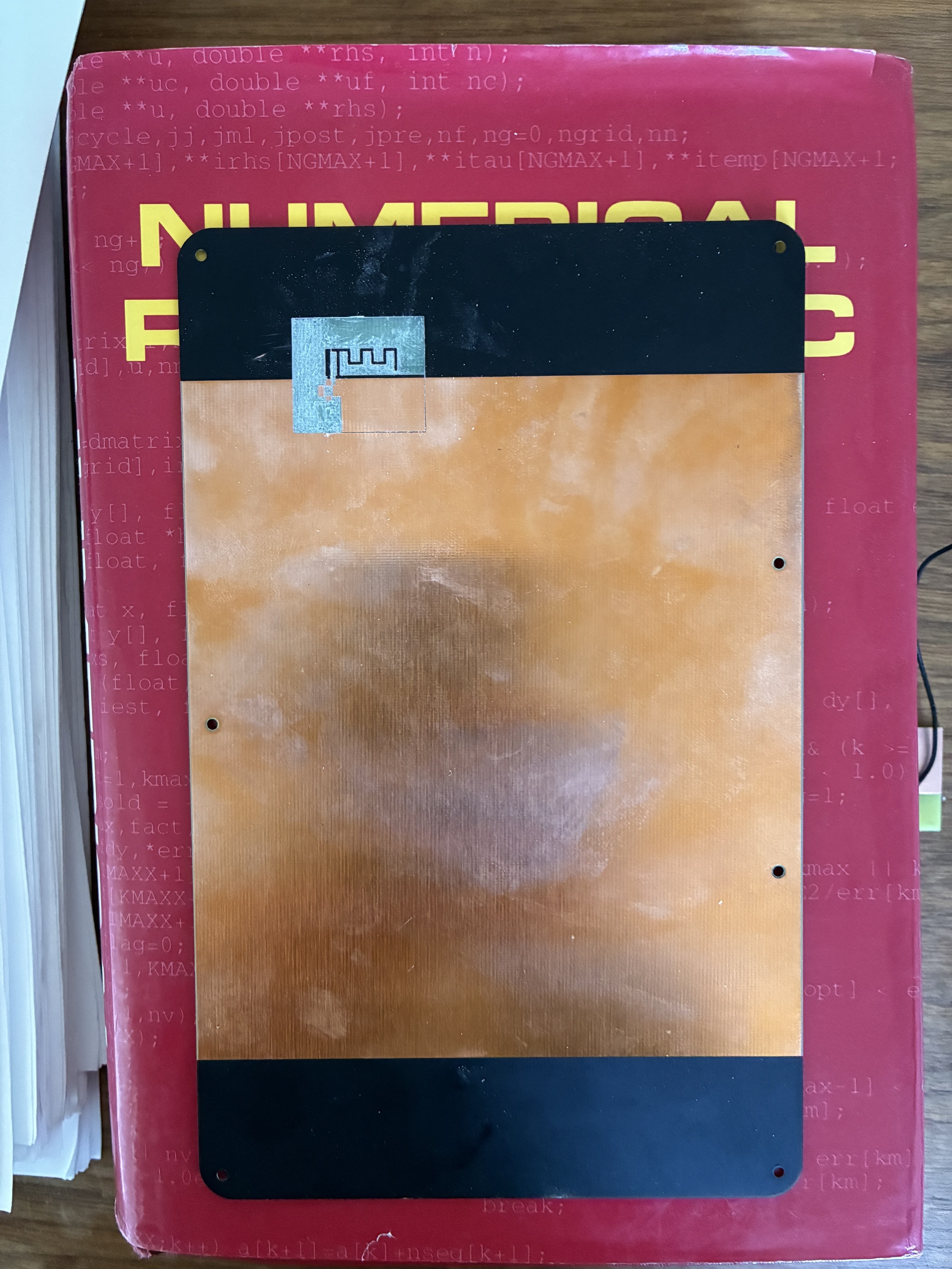
Well, today we finally found the reason for the back plate attenuating the signal much more than it should: under the black soldermask next to the copper heatsink area, there’s actually copper, and not, as intended, no copper.
I was looking into PCB antenna designs. There are designs available “out there”, including kicad footprints for PCB antennas. These may need tunning for the copper thickness, etc but in principle could work more or less out of the box. One example is here:
We could have the antenna ontop of the lid exposed, like the MNT copper logo in the heatsink and connected with vias to the bottom and a surface mount connector like this:
The heatsink can occupy most of the lid, but we can leave a chunk for the antenna with nothing on the bottom. Some antenna designs include a ground plane on the bottom layer, and that affects the radiation pattern.
I don’t know anything about antenas, so any feedback would be very welcome!
The good news is that trying something like this is relatively easy and cheap, and as I mentioned I can run this by a grown up in the area as well
By the way although its too bad this happened its pretty awesome that you found the source of the problems.
This probably means there is an “easy” fix removing the copper, although I will continue to pursue the embedded antenna.
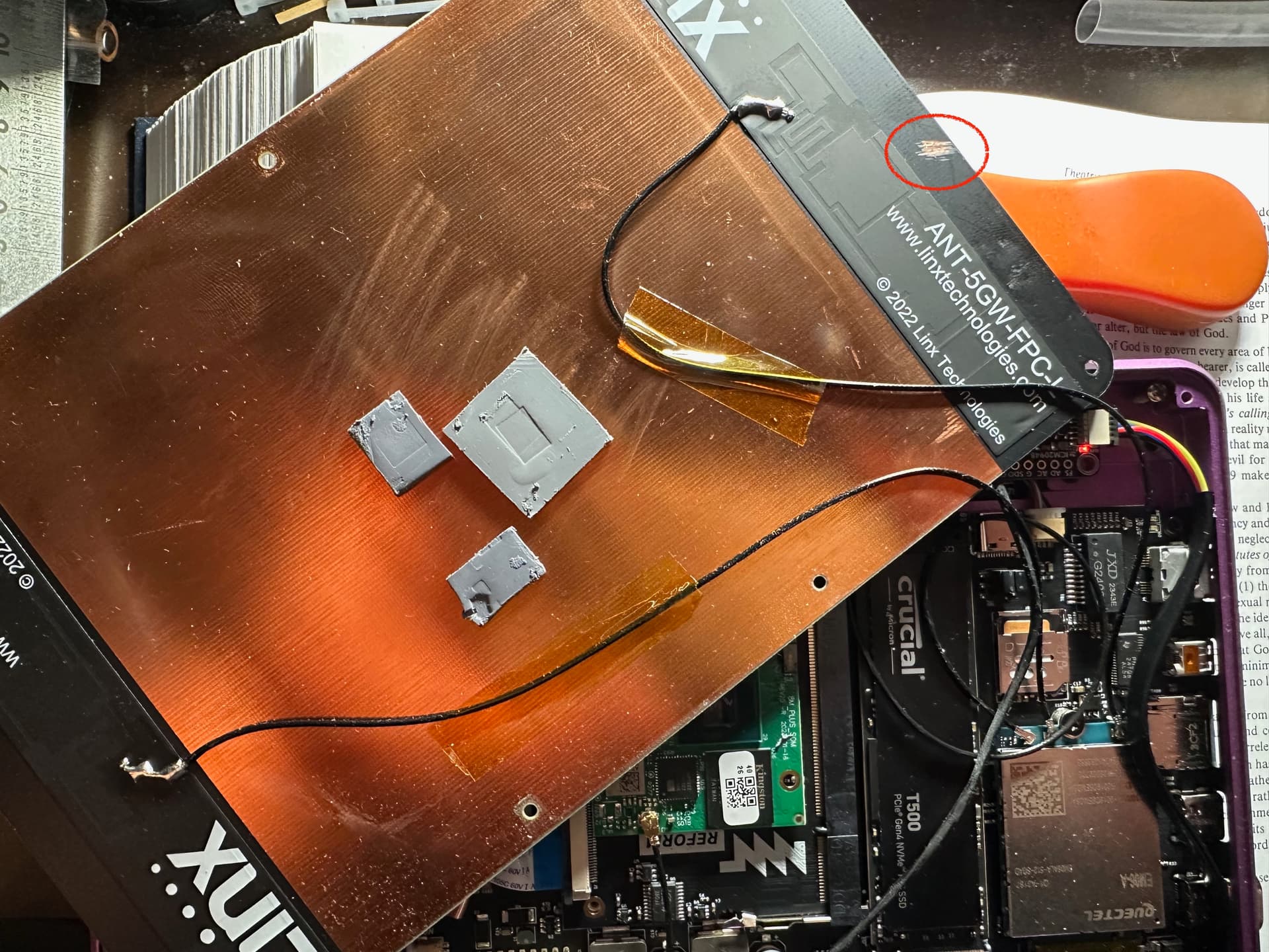
I did/am doing a quick experiment to get more data for possible solutions. I used the kicad pcb source to 3d print q lid with PETG.
So there is no heatsink, and the lid is melted plastic. I dont advise anyone to do this.
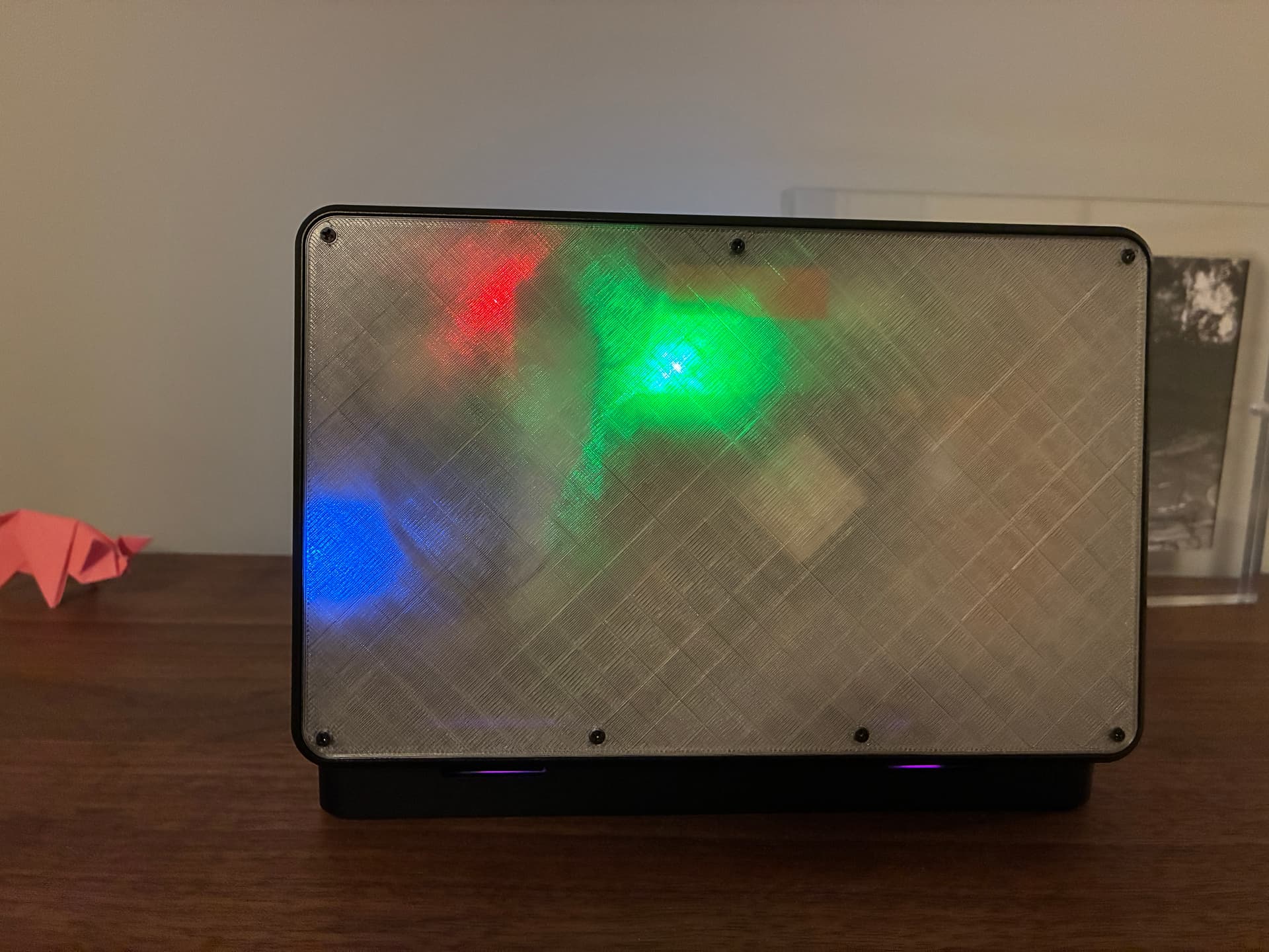
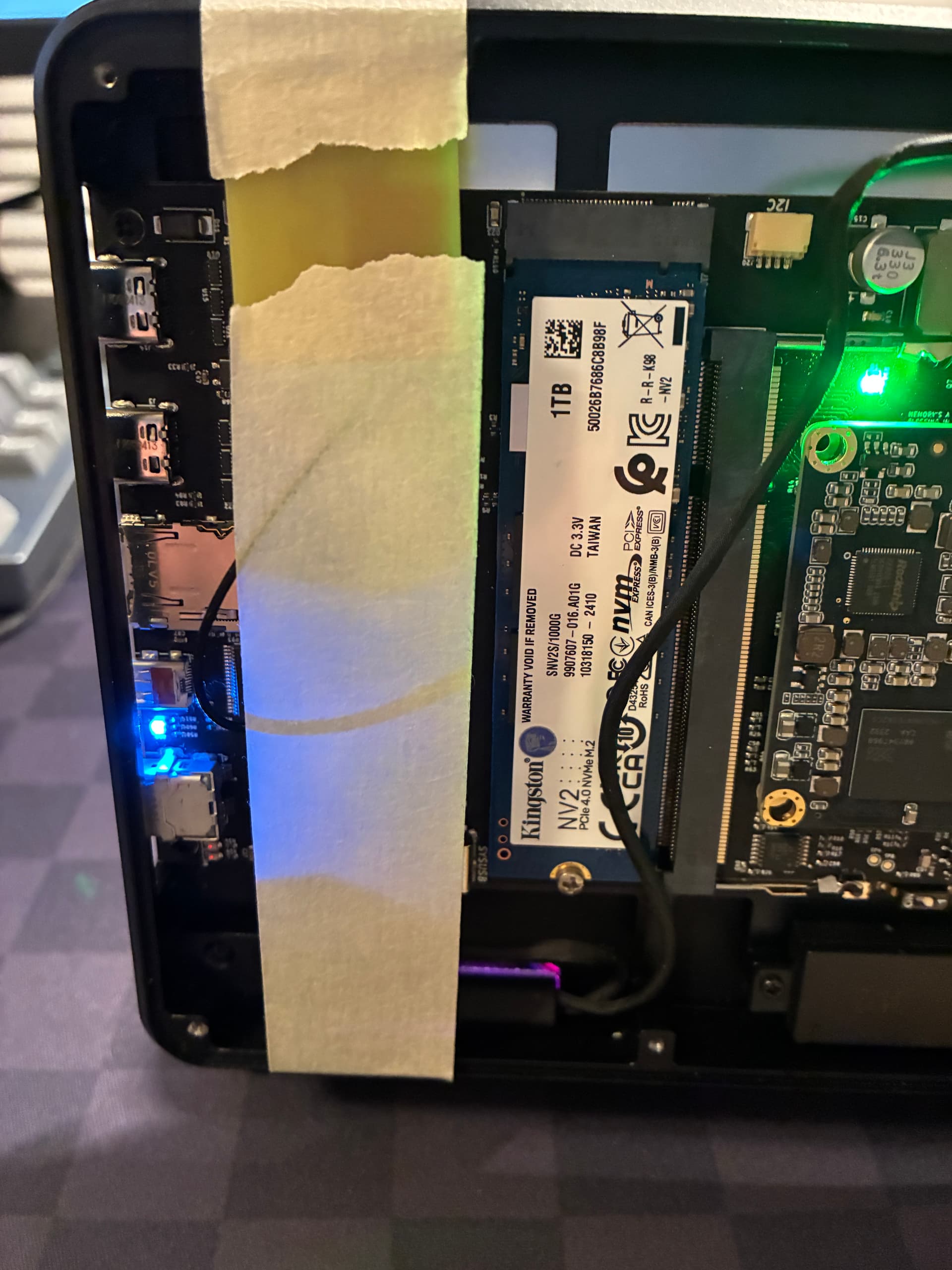
The good news is I have an antenna attached to the inside of the lid and I am getting great reception. Probably as good as I was getting with the antenna outside, and better than most devices.
I dont know if the PCB material without copper would attenuate the signal more than PETG.
I placed a Laird antenna on the lid near the top,above the processor module after trying another placement that didnt work as well under the wifi card.
Above the green light in the picture.
oh wow! that explains a lot, especially how well (comparatively) the full aluminum top case works.
This is good to know! I’ve been thinking it might be nice to design an interlocking plastic top case with a metal heatsink for the best of both worlds. (But maybe fr4 would be good enough, too?)
I guess dual adhesive LTE antenna worked better than the supplied one, because the one was placed closer to the more open WiFi antenna side window… Original LTE antenna I placed on the USB/HDMI side and reception and transmission was terrible.
I am wondering if MNT can produce the new lid with copper only in the middle? Might as well with WiFi antennae, LTE antennae and GPS antenna printed on?
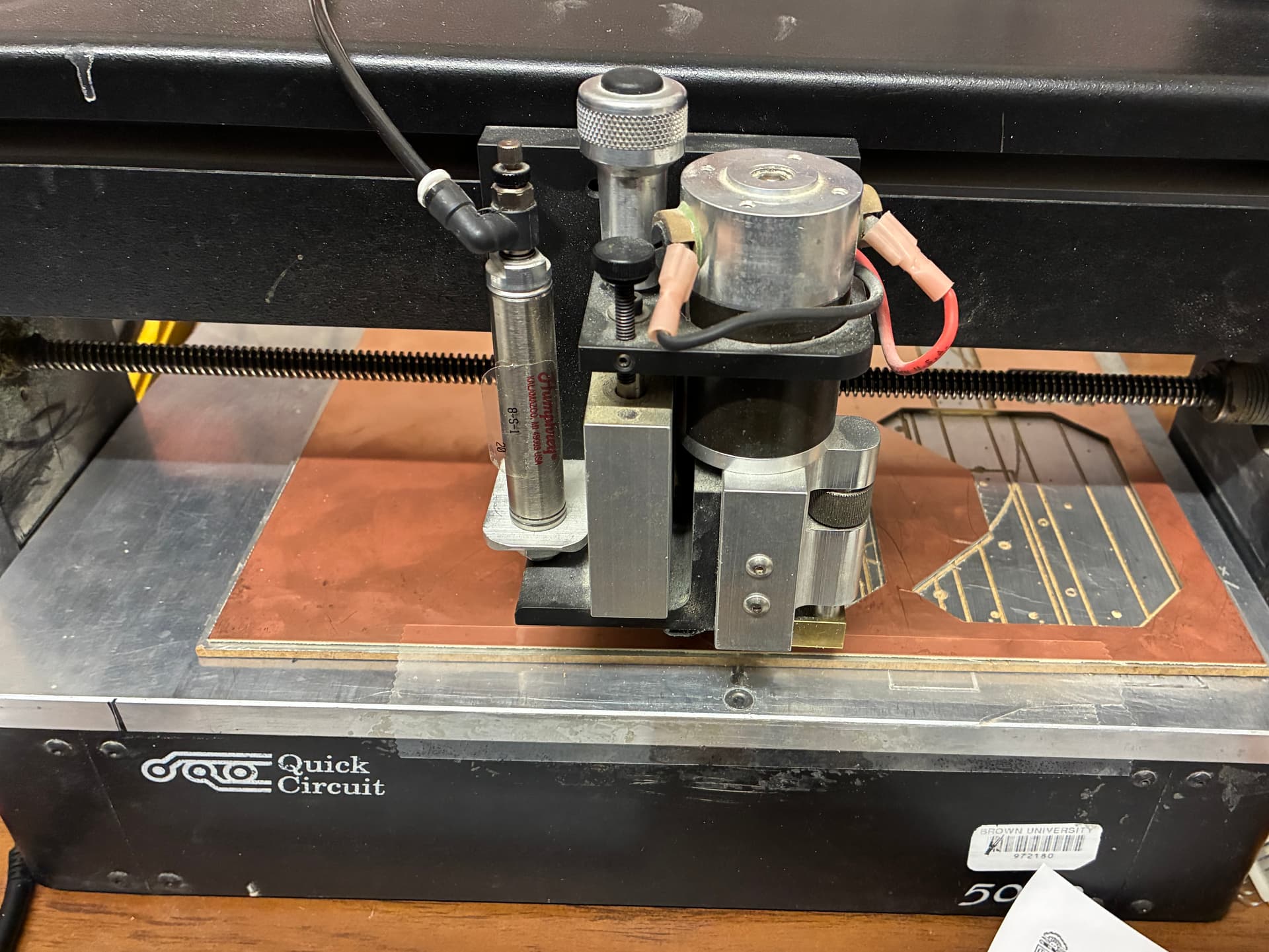
I am getting a demo of this PCB mill on Monday. Belongs to a friend with a lab down the hall.
I’ll try to mill an antenna PCB on a fresh board and if all goes well maybe try do it right in the pocket lid.
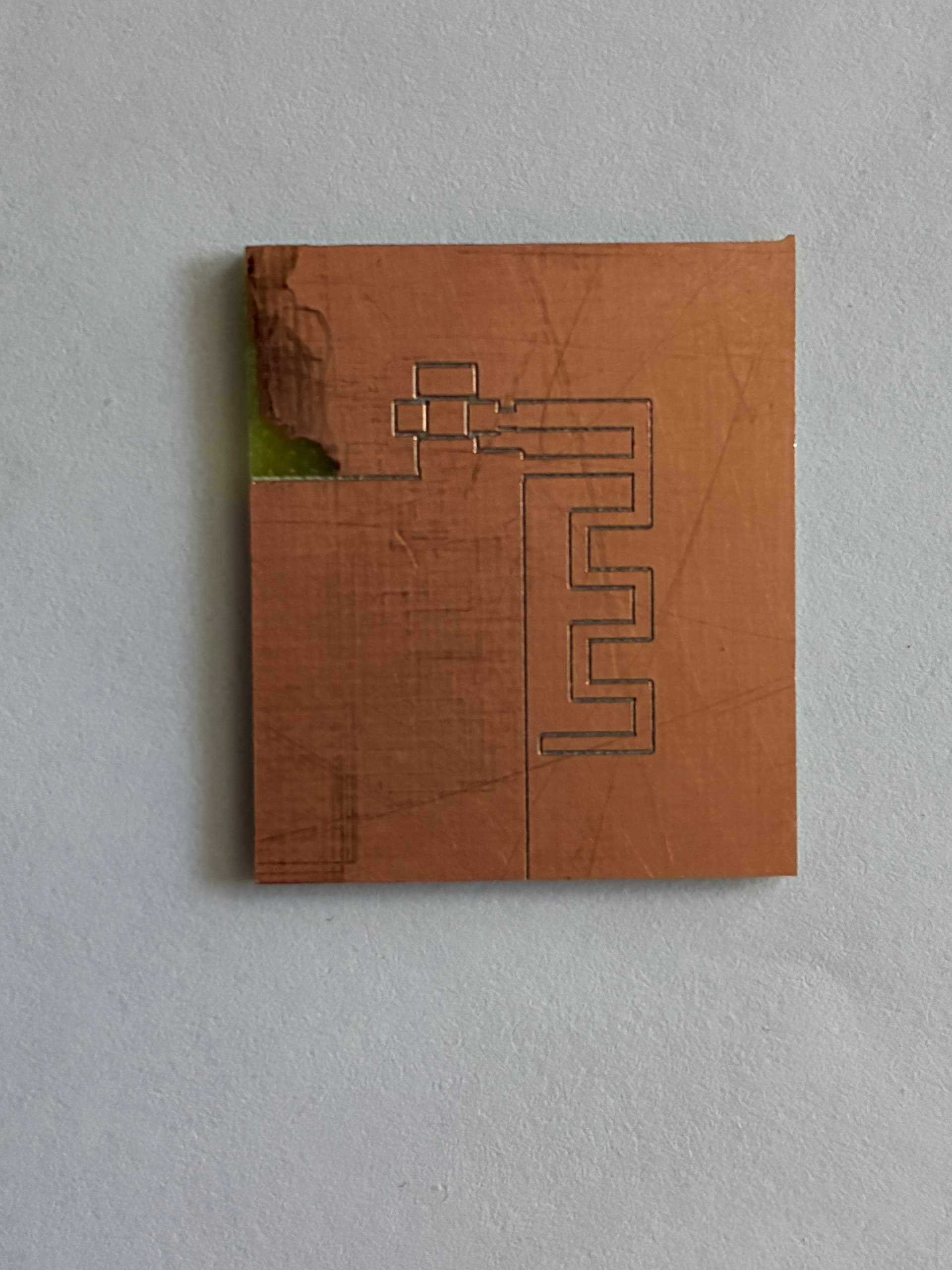
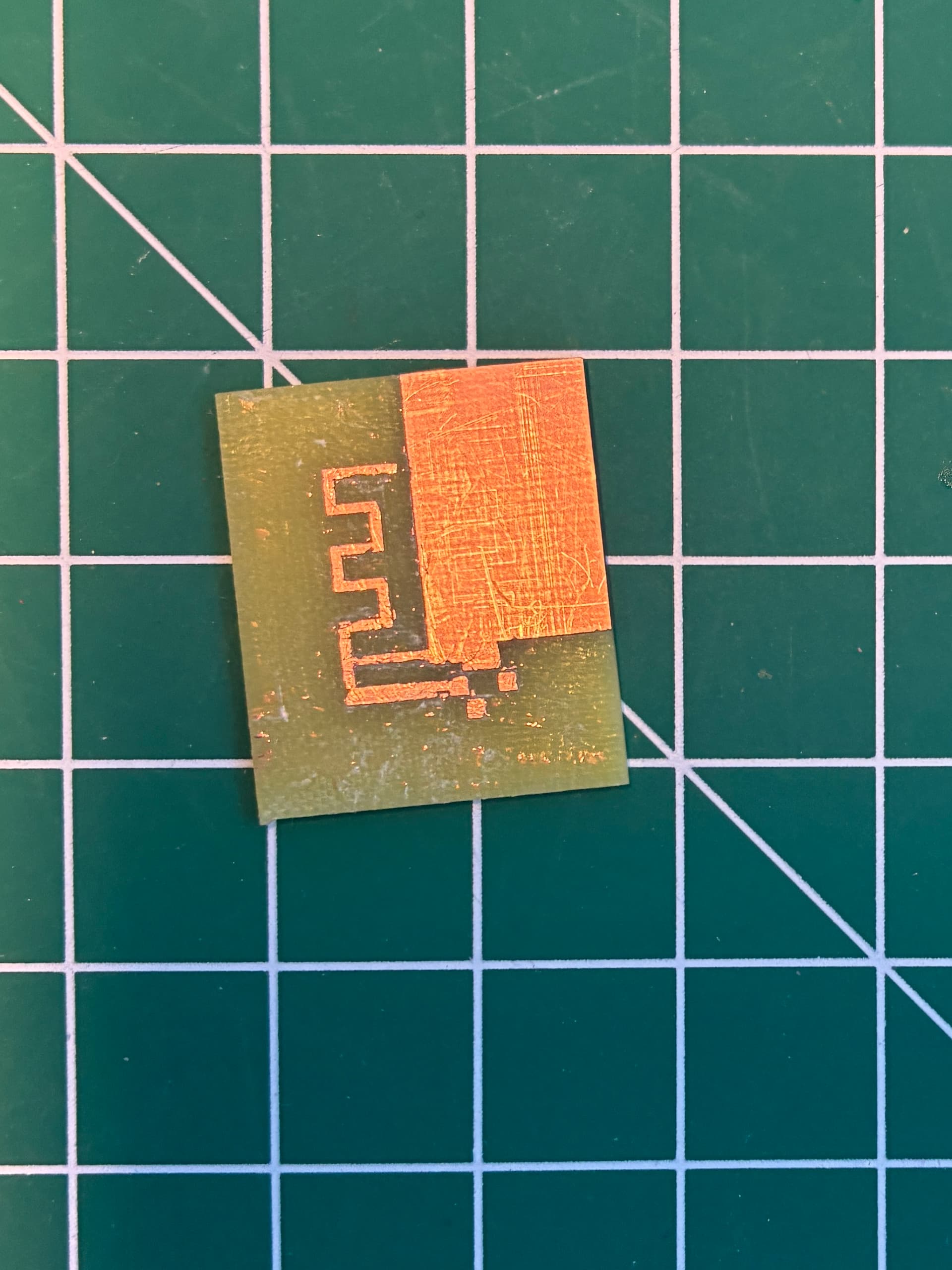
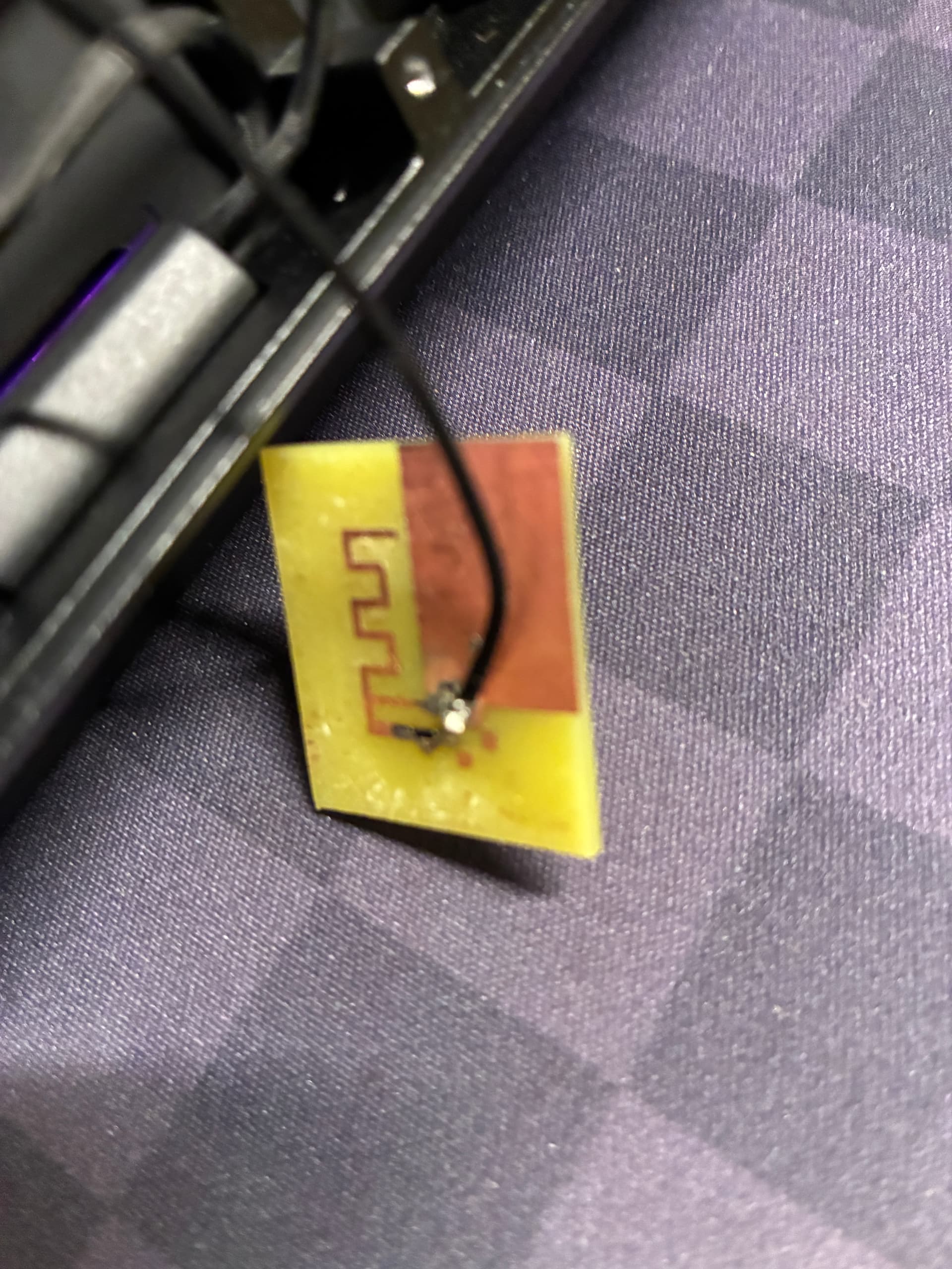
Today I printed a test PCB antenna. The PCB mill is apparently not so good at scraping “big” copper areas. Although it should be able to do it my friend who owns the machine said they don’t like to do it and it doesn’t work well. Instead I made only separation cuts and scraped some copper with a razor blade – you can kind of pell it but in small chunks.
Running like this I get good reception (similar to Laird antenna without lid) based on a few minutes test with wavemon and playing a youtube video in two locations at home.
So this is promising! There is no reason it shouldn’t work but having not experience before I wasn’t sure what to expect.
Later this week I’ll try to engrave my pocket lid directly to be able to test more.