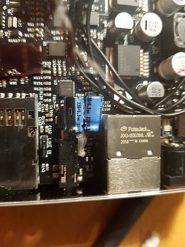
Hello all. I was re-reading the March update on Crowd Supply, and noticed the following piece about the new v2.5 revision of the Reform motherboard (Numbering added by me):
A revised v2.5 MNT Reform motherboard is also done, fixing some bugs with the initial design as well as switching parts out based on availability. The main improvements are:
1: Lowered headphone lowcut filter for improved bass response
2: USB-C replaces microUSB as the LPC flashing connector
3: Lowered power LED brightness
4: Fixed current leak through balancing circuit that could bypass missing cells
5: Fixed main buck converter enable behavior under low voltage condition
6: Fixed charger control circuit that previously required a factory resistor bodge
I began pondering the feasibility of applying some of these tweaks to my existing (v2.0?) to create a blend of both. (v2.25? v2.45?).
I don’t care that much about some of them. #2 isn’t important to me, it would be a very involved fix and wouldn’t achieve any notable benefit. Same with #6, I don’t mind the bodge at R53. It just reminds me that this was built by humans, too :^)
#1, #3, #4 and #5 all seem quite interesting to me.
I know #1 should be feasible. C147 was changed from 47µF to 220µF (with a helpful label to make it easy to spot :D). It’s in a bit of an awkward spot between the Ethernet jack and the headphone jack, but my TS100 is slim enough to work there.
I know #3 is also certainly feasible, just replacing R164 and R33 with higher value resistors should do. I’m not sure exactly what the change was, though. I tried comparing the schematics between the old and new versions, and both versions specified 1k resistors. Maybe the diodes were changed?
#4 might be feasible? I’m not sure how critical this fix is, but I see a 100k resistor (R86) added between Vref and Vtemp1 of the balancer, and R79 was maybe changed somehow? I don’t know what all the symbols mean, I’m very new to reading schematics!
#5, don’t know. It seems like Q13 and Q14 near U7 and U12, respectively, were both swapped for a resistor and diode pair? Are Q13 and Q14 transistors? I’m not sure. Maybe feasible. Again, don’t know how important this fix is.
Regardless, I most care about #1 and #3, and those seem the easiest to do.
So I’m hoping we could document some of those here to figure out how feasible applying these at home with decent soldering skills would be. I might be able to find a hot air station at the local hacklab too, it’s been 12 years since I did any significant SMD work, and these components are tiny!
I also don’t know how reasonable it is to acquire these tiny passive components in small quantities. Are there any nice assortments of these SMD parts available in varying sizes and specifications? It would be nice to stock up on lots of different ones at once, just to have them on hand. I’ve been meaning to put together a more permanent electronics workstation in my home office anyway.
Thanks for reading! I’m excited to learn more about these changes, and trying these out on my hardware.
