I 3d printed a custom lid / back panel

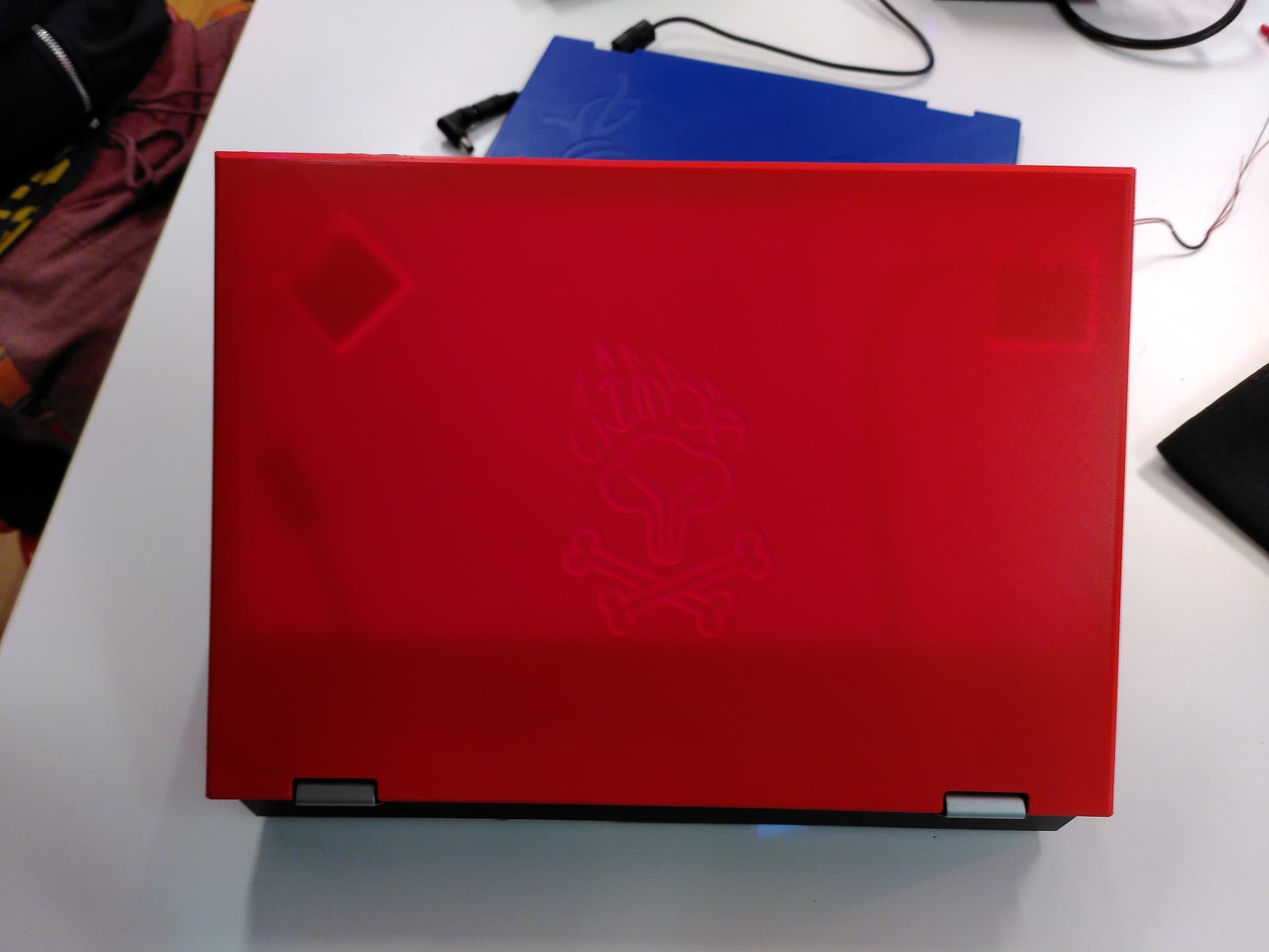
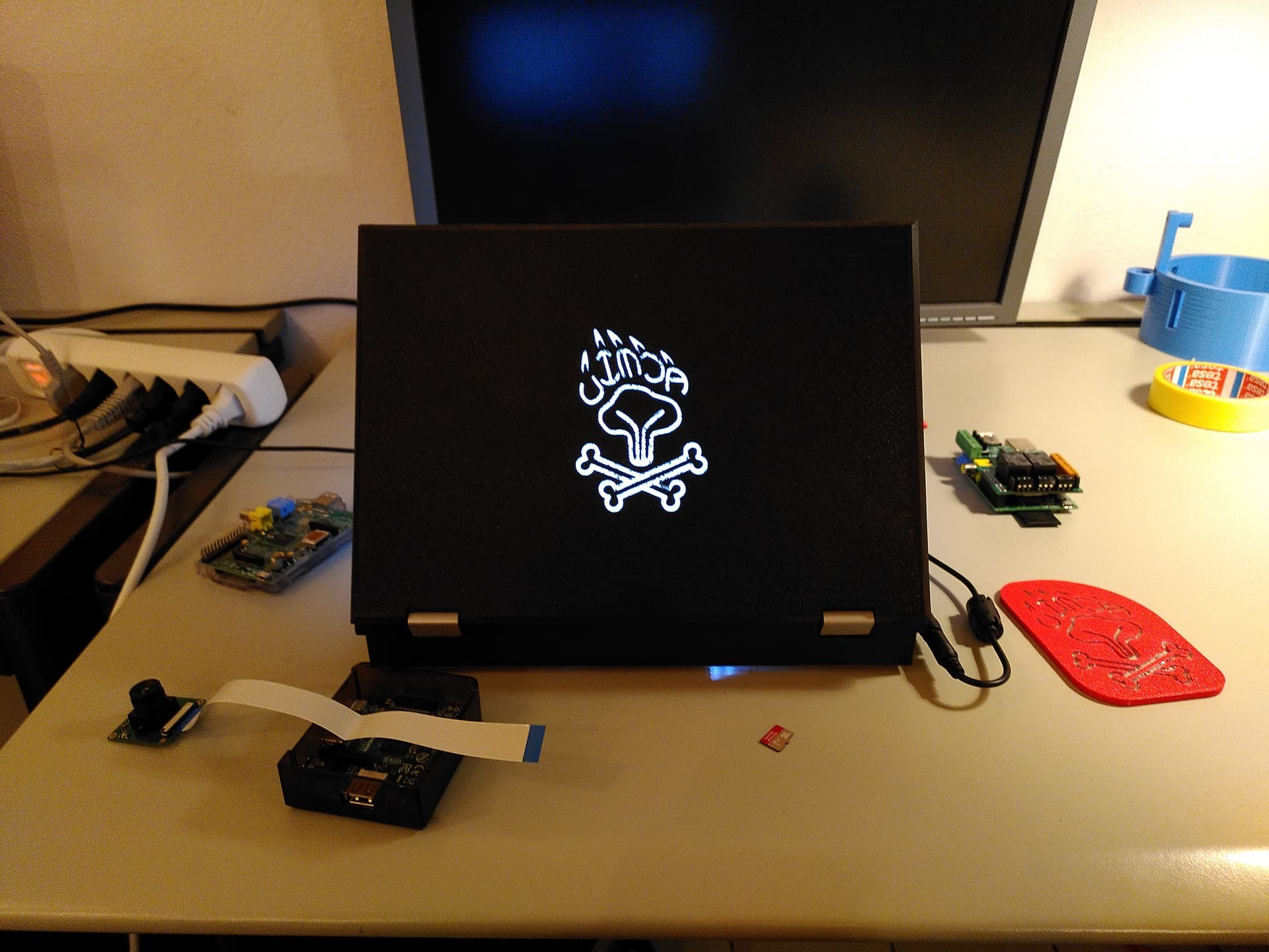
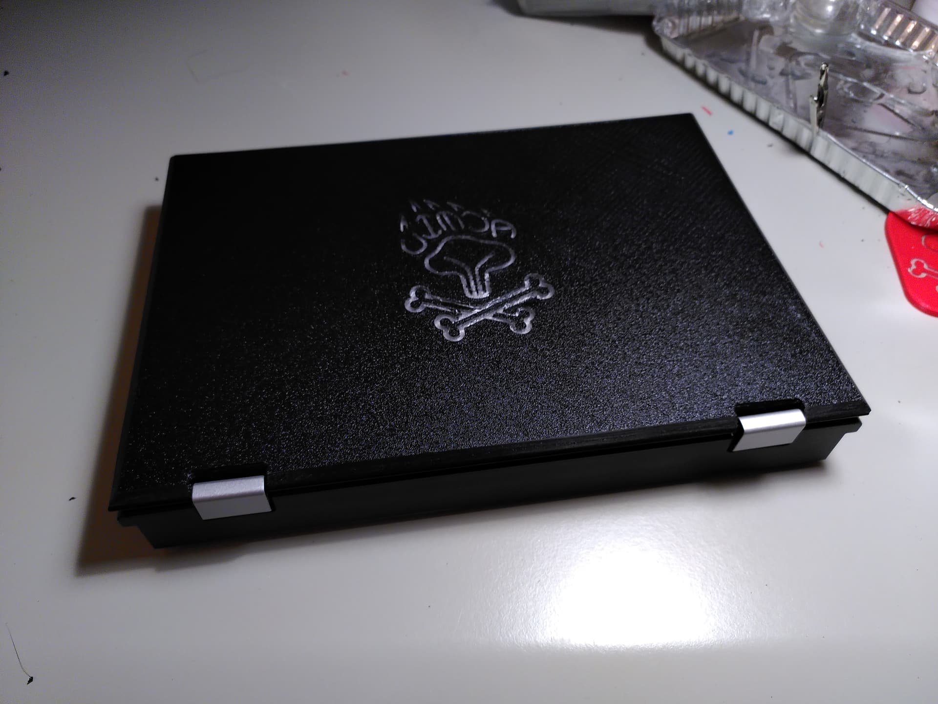
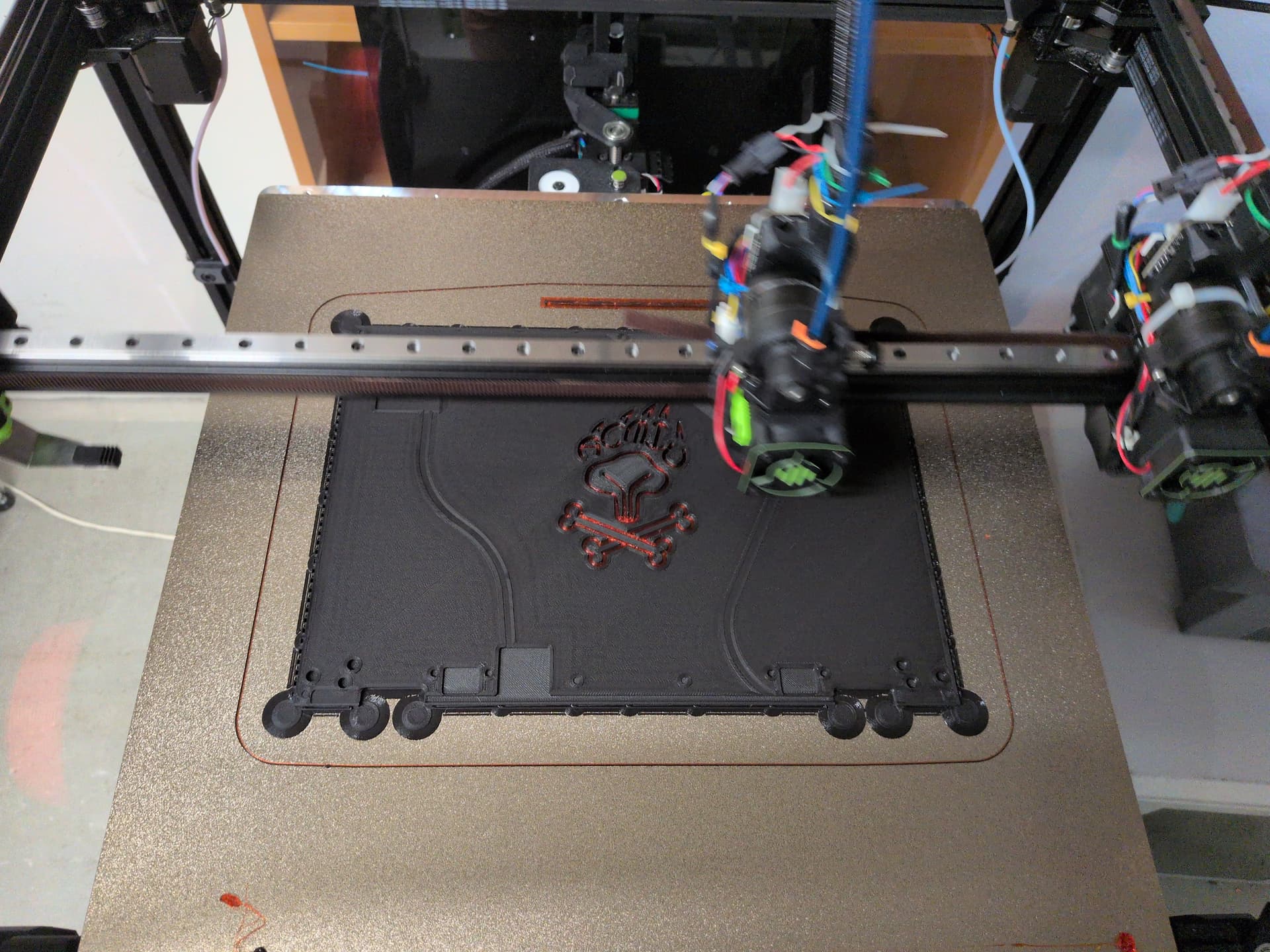
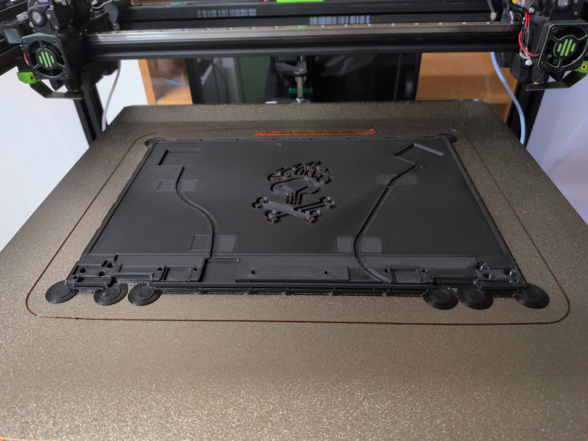
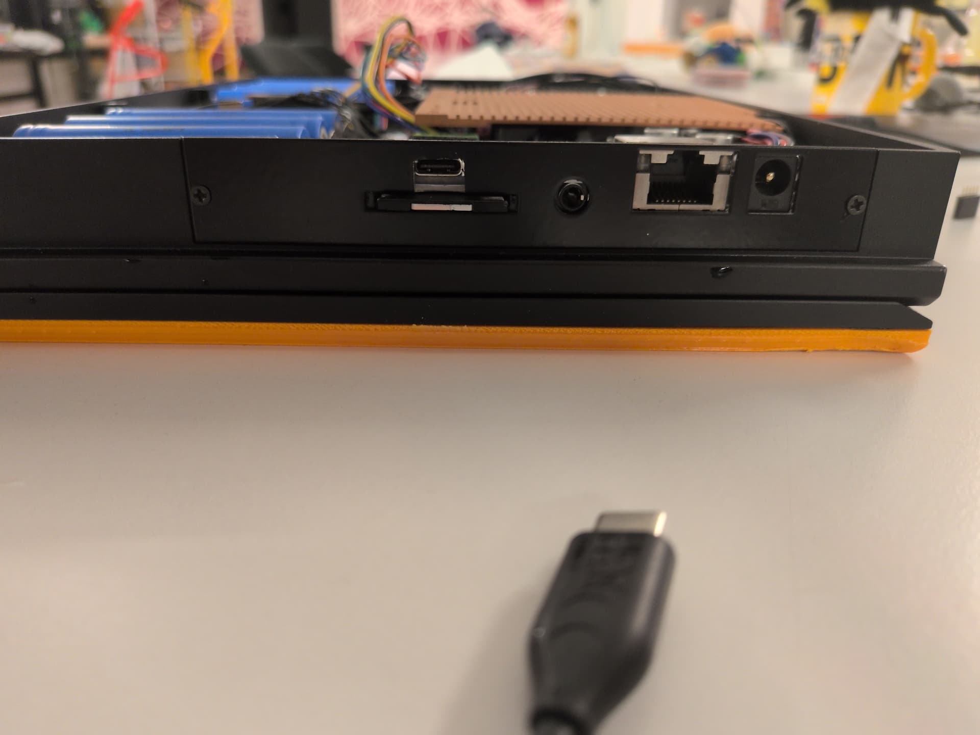
I 3d printed this custom lid for my mnt reform 2.

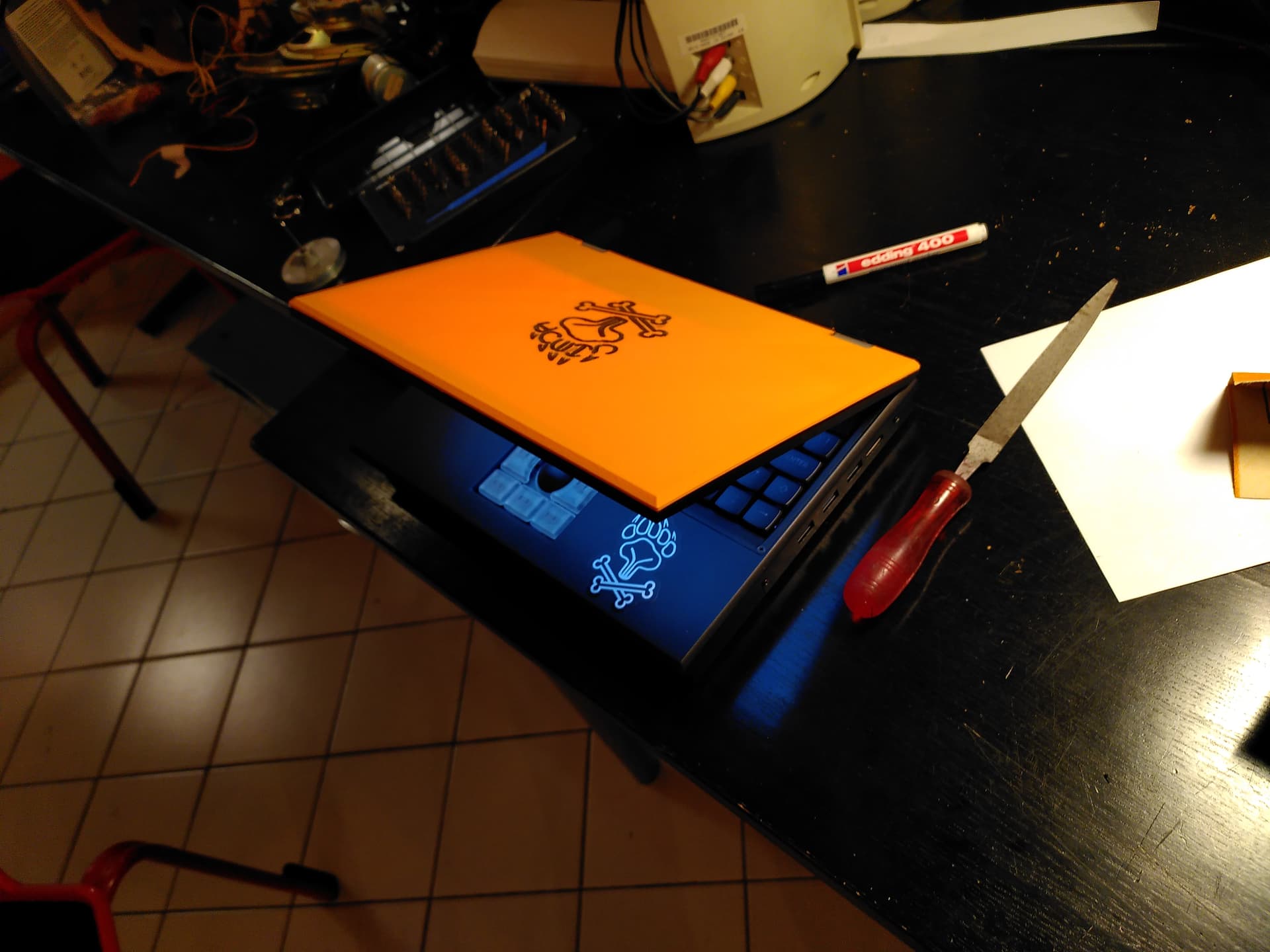
This is my second attempt at this. This is not currently a good solution but just about good enough for me to leave it on and use it for a while, hopefully until my next revision.

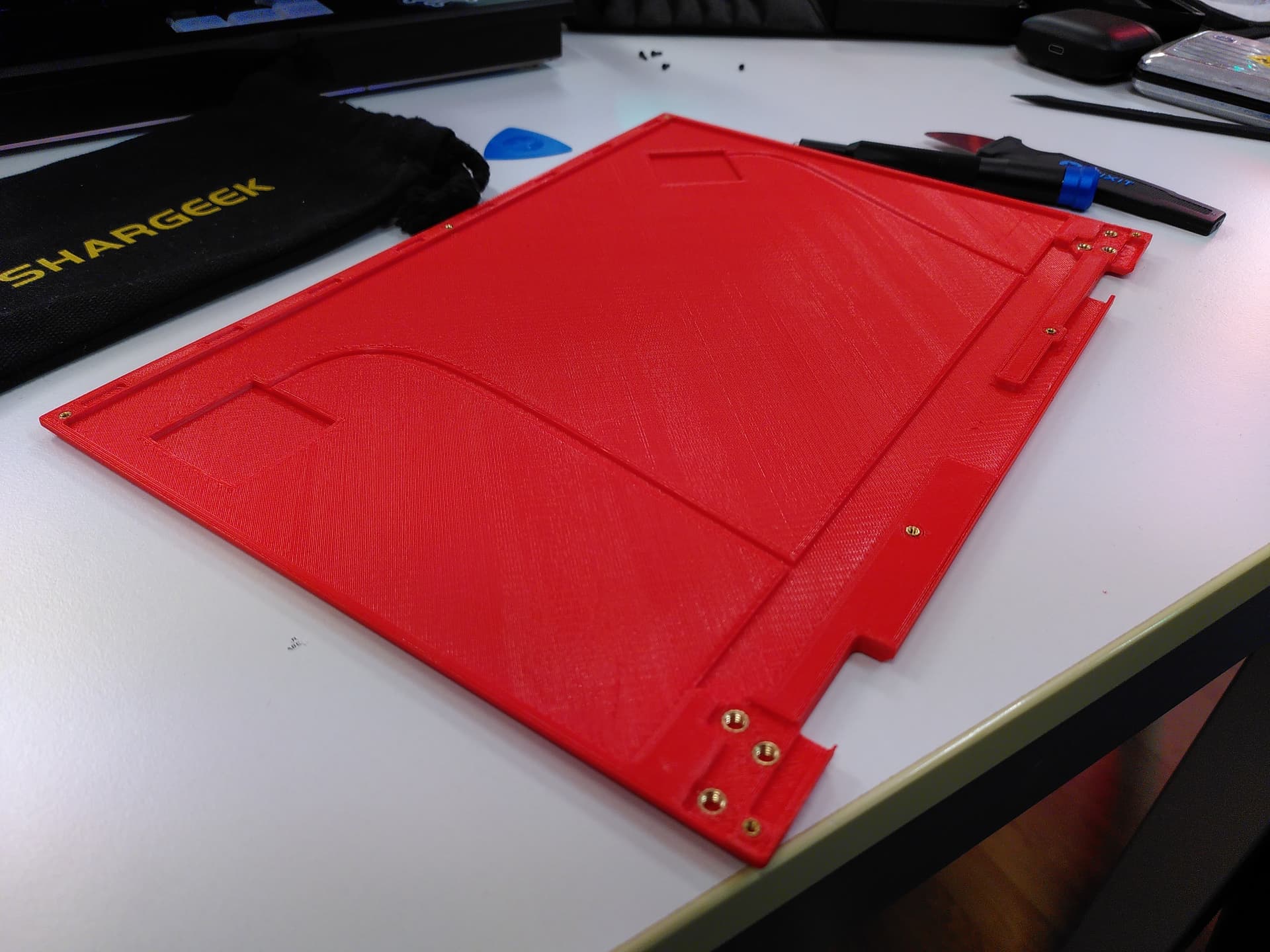
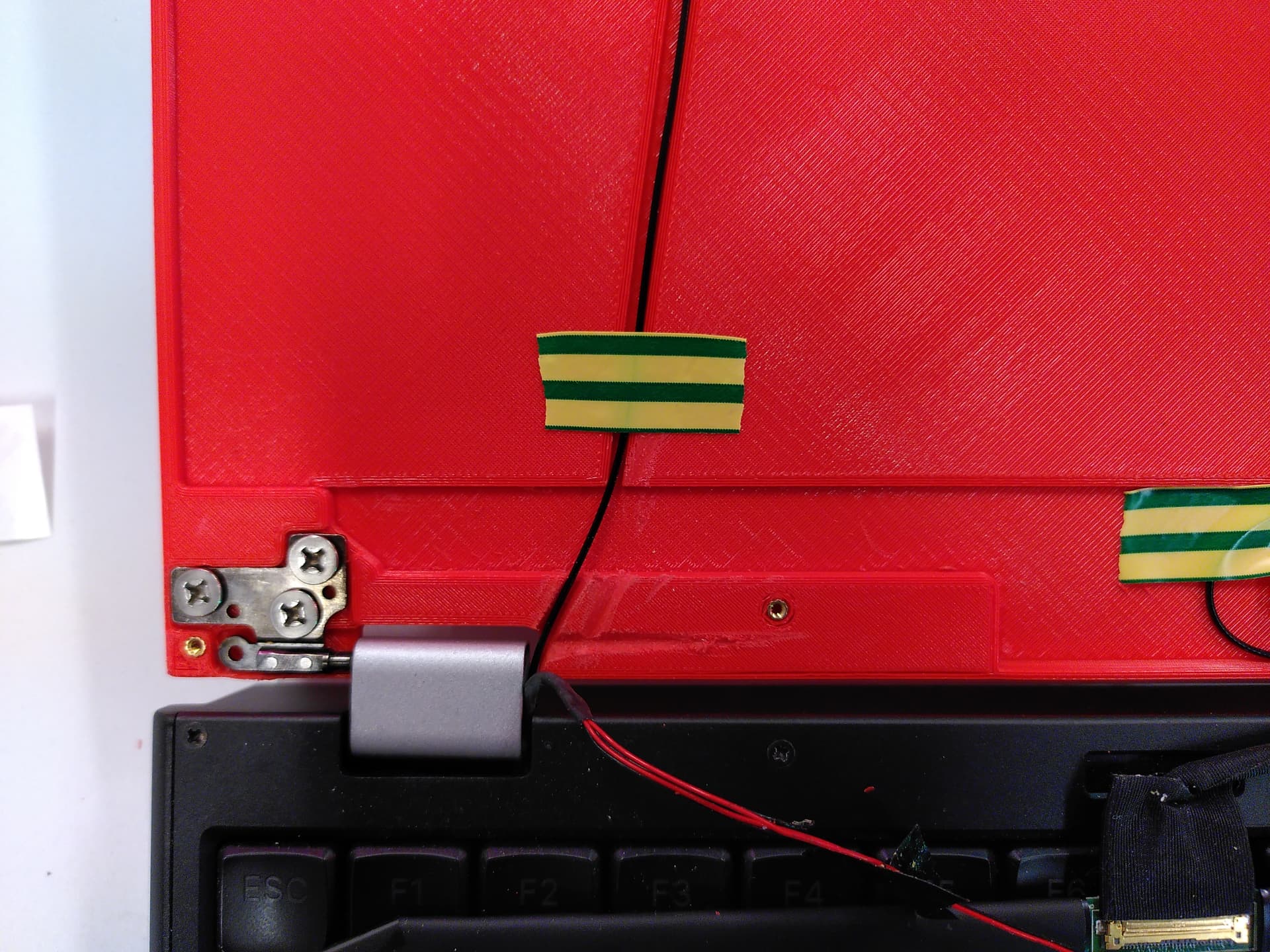
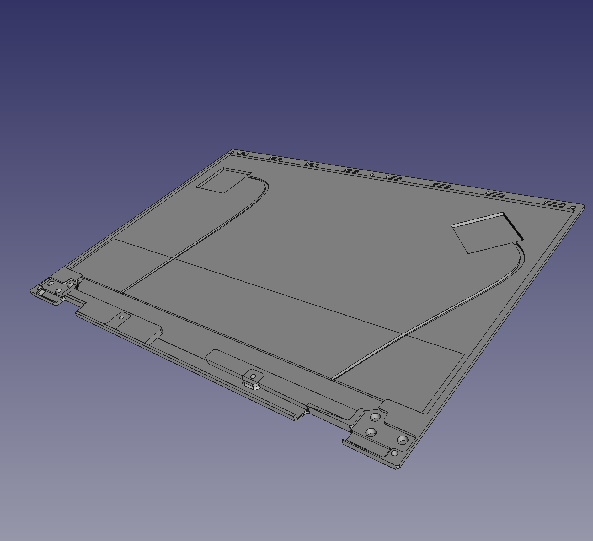
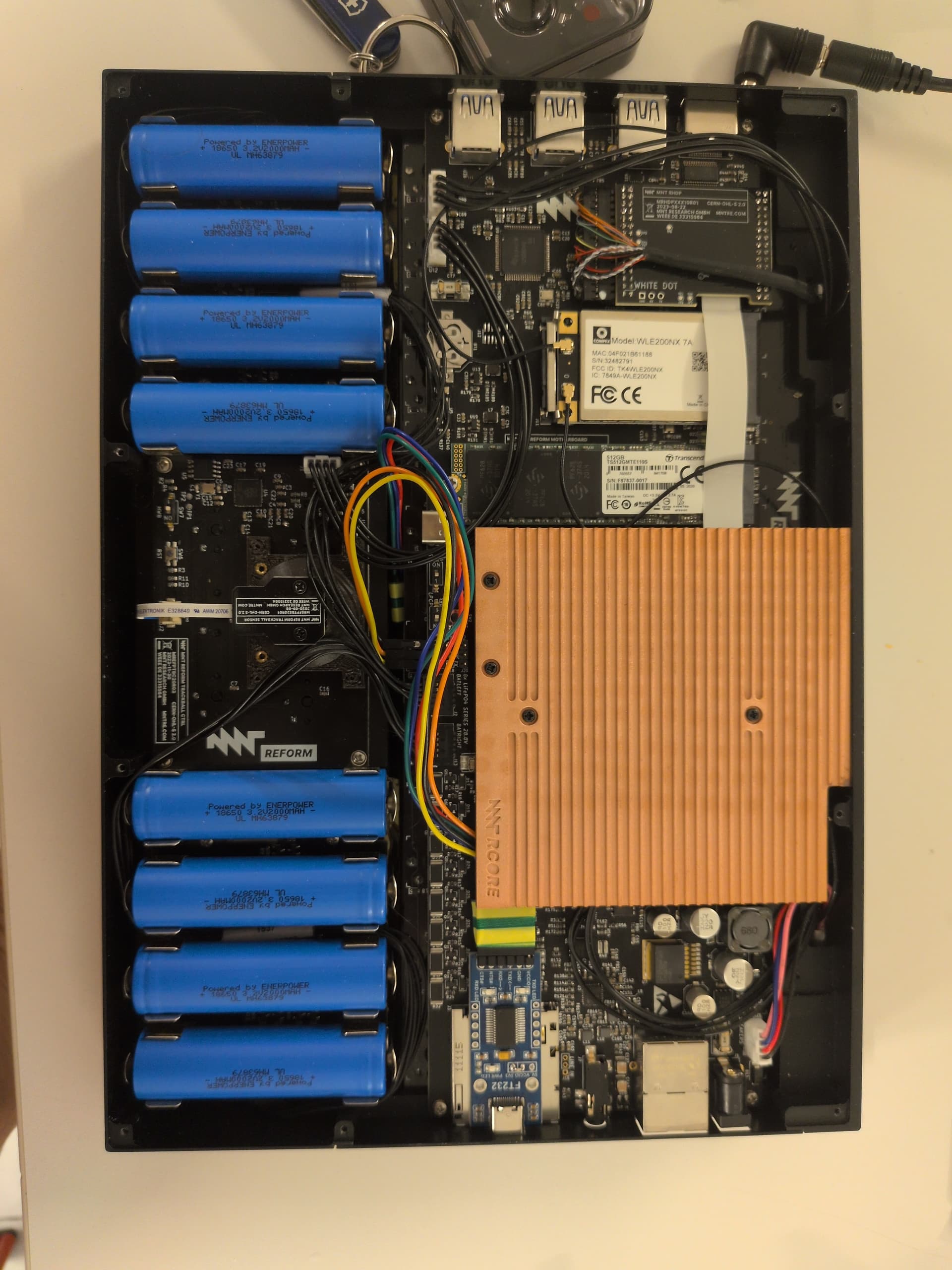
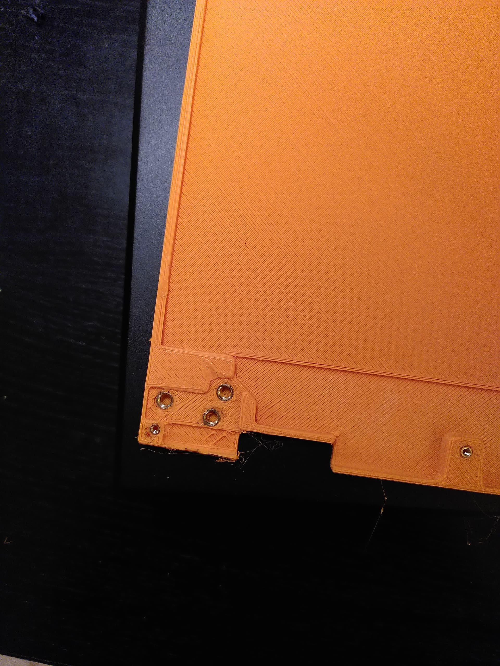
I modified the .step file from the mnt repository using FreeCAD and made some optimizations for 3d printing. Some of them are based purely on guess work, others on earlier attempts at this. The most important change I made is making the screw holes big enough to take threaded inserts. This was actually suggested by @minute and it does wonders.

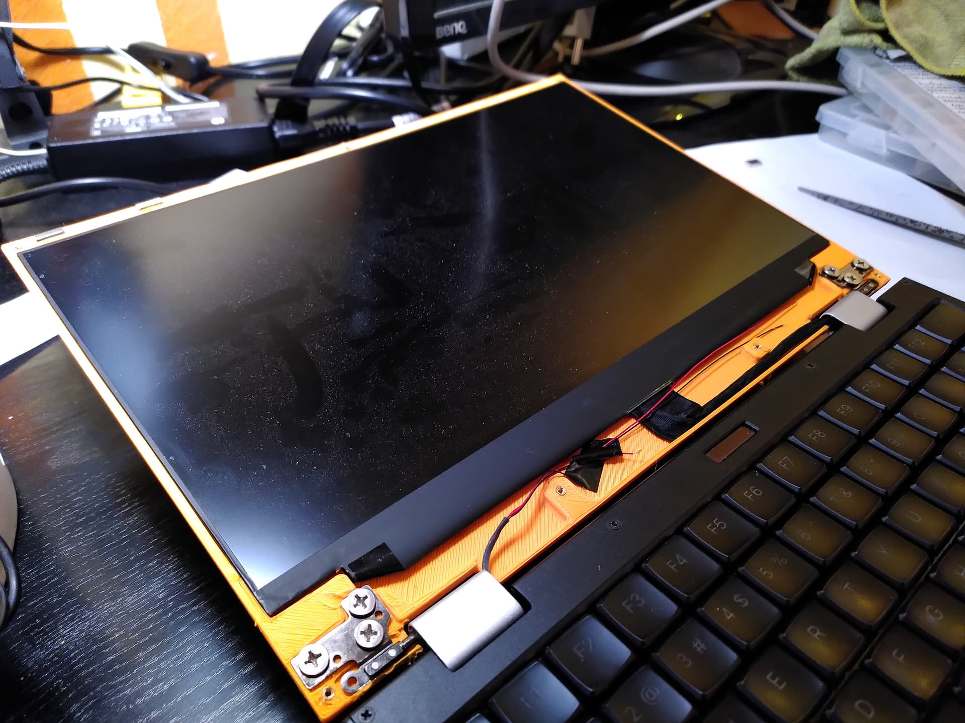
The metal back panel is optimized for weight, but with 3d printed plastic that isn’t much of an issue, so I made the panel thicker wherever possible.

This print has many issues. For one thing I printed at low quality and low infill. It is not intended to be the final version of this, I just wanted to see if everything would fit, which it did. Also I used a Creality Ender 5 Plus that I purchased specifically for this purpose and while the printer is large and cheap, it is also pretty crappy. I have already ordered a couple of upgrades for the next run.

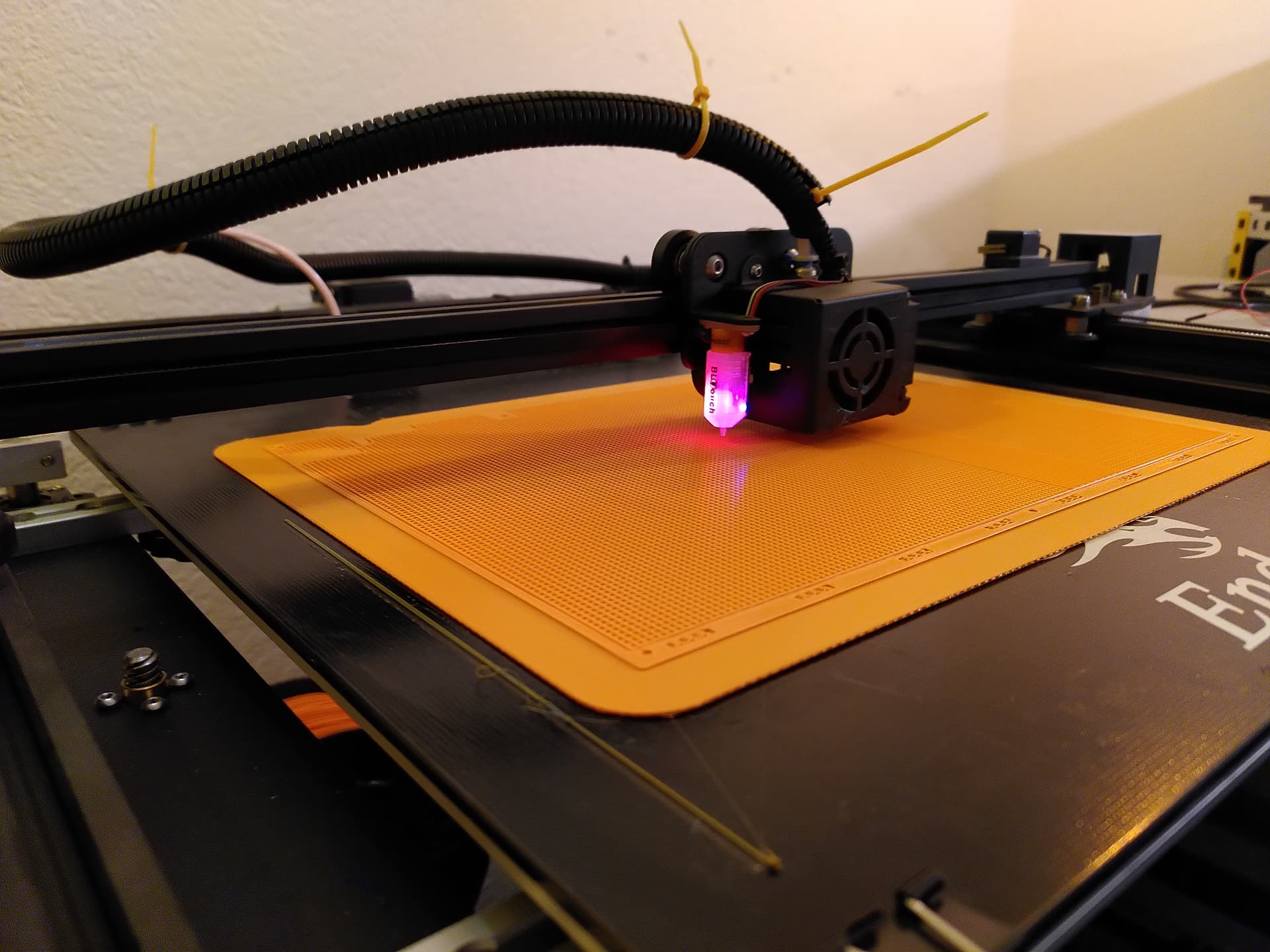
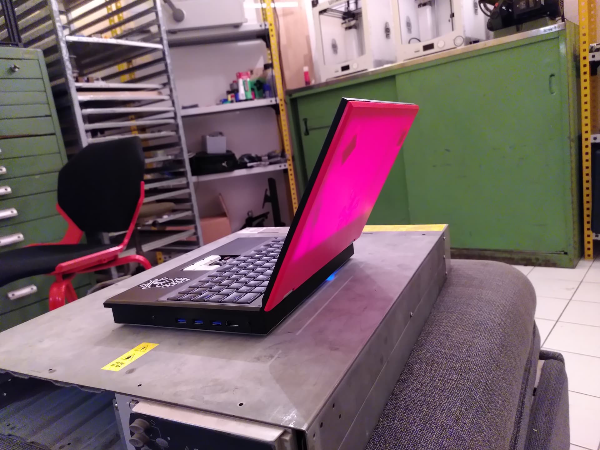
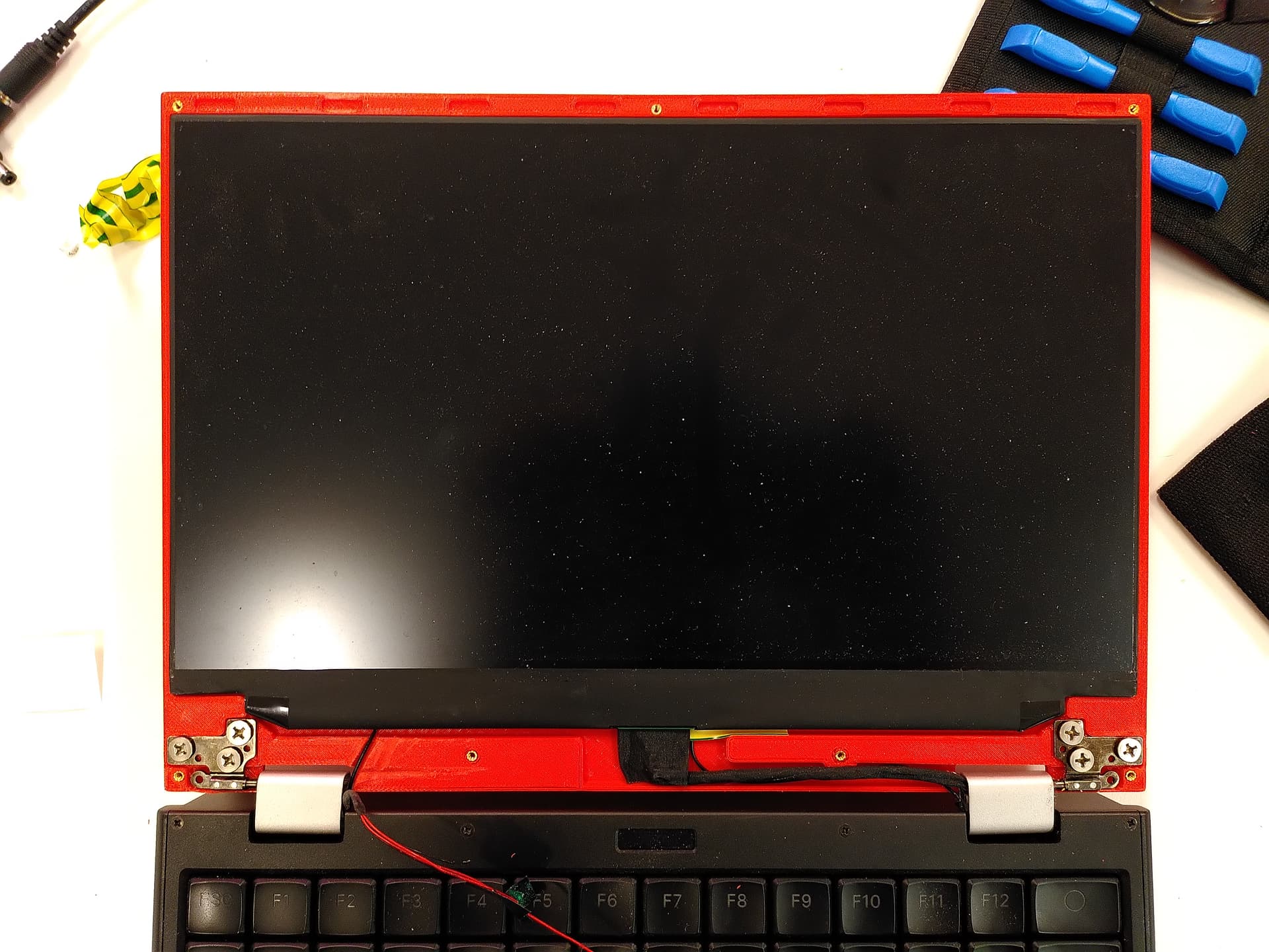
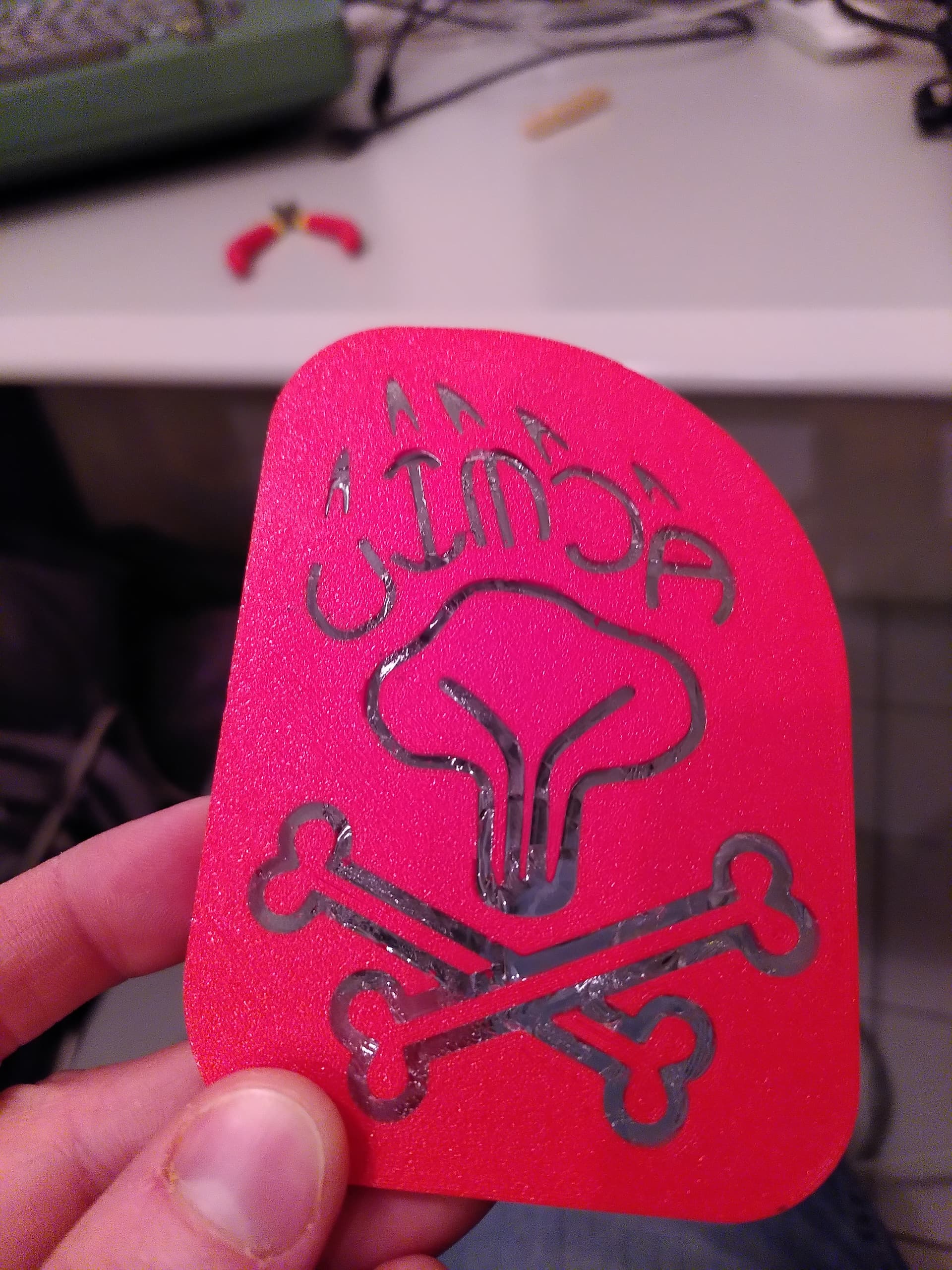
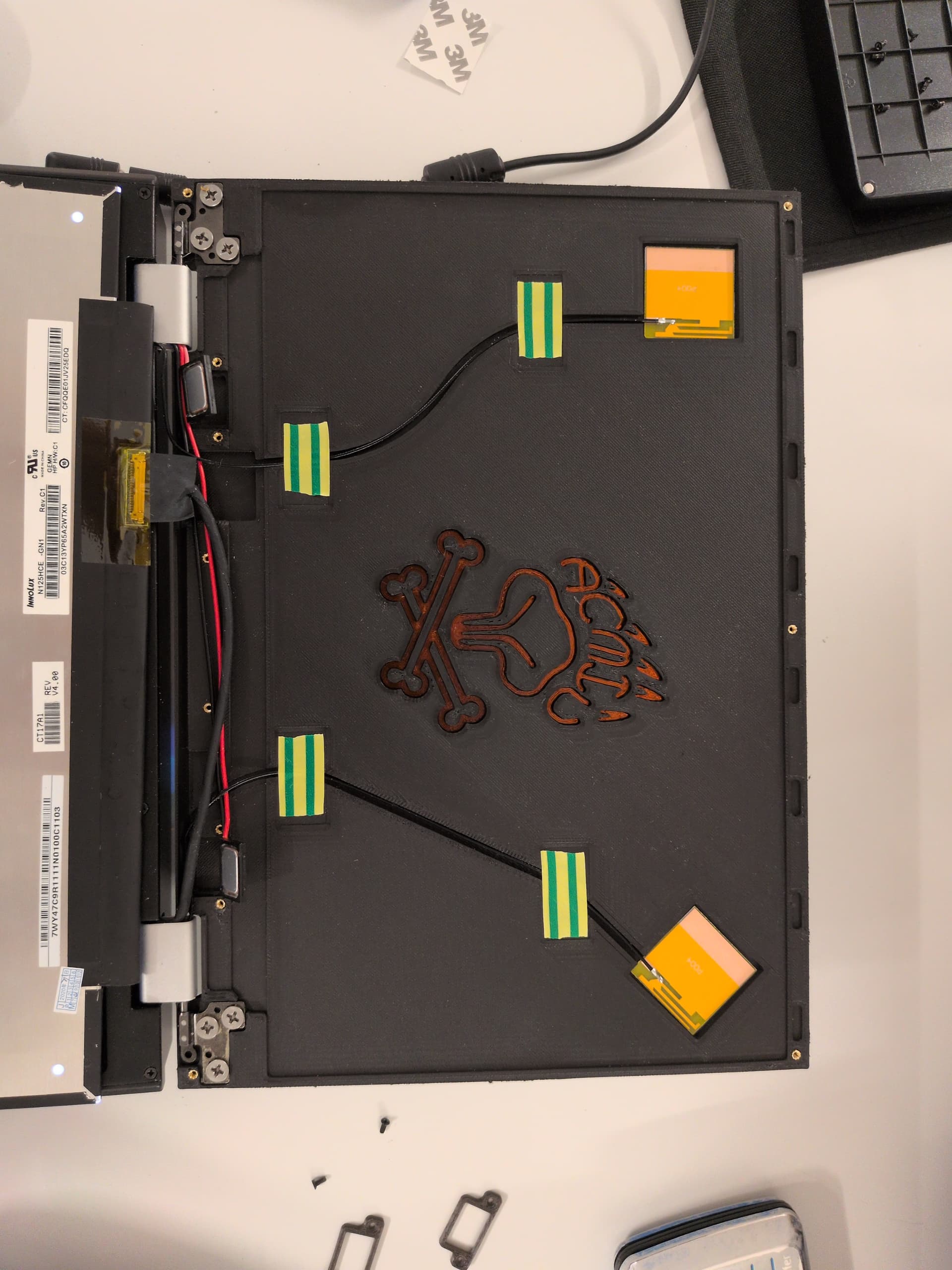
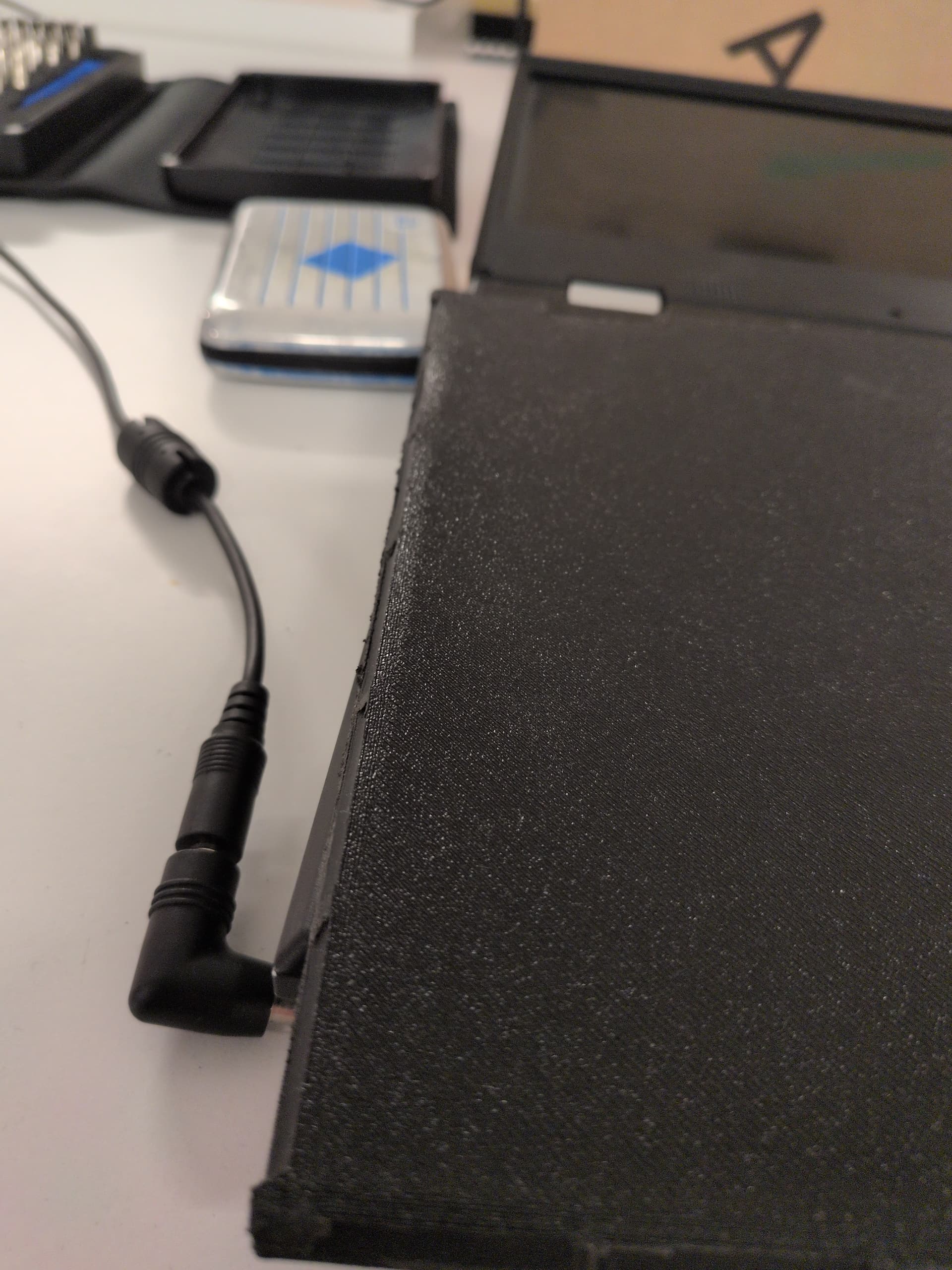
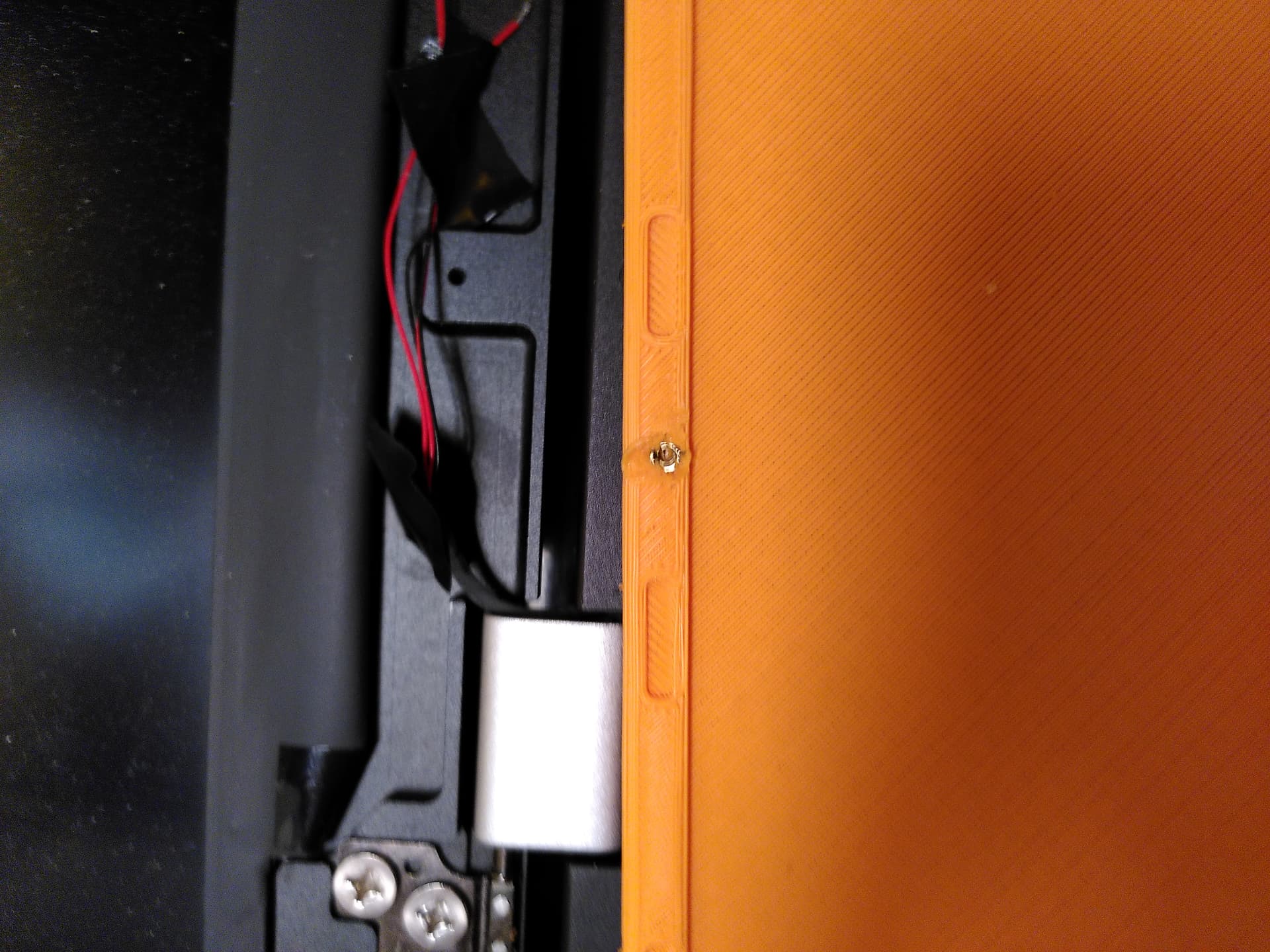
The issues I have with this print include massive under extrusion to the point of de lamination of layers and one piece breaking off when I tightened the screw. Also the model is slightly too long (front to back) resulting in a bend when mounted. Not quite sure what caused that. Also this was my first time installing threaded inserts and I did it using a soldering iron with a regular tip, which was not well suited for the task. Finally with the low infill and the thing being made from plastic, it is not actually very sturdy. When I press on it from the back, it shows up on the LCD in the front :grimacing:

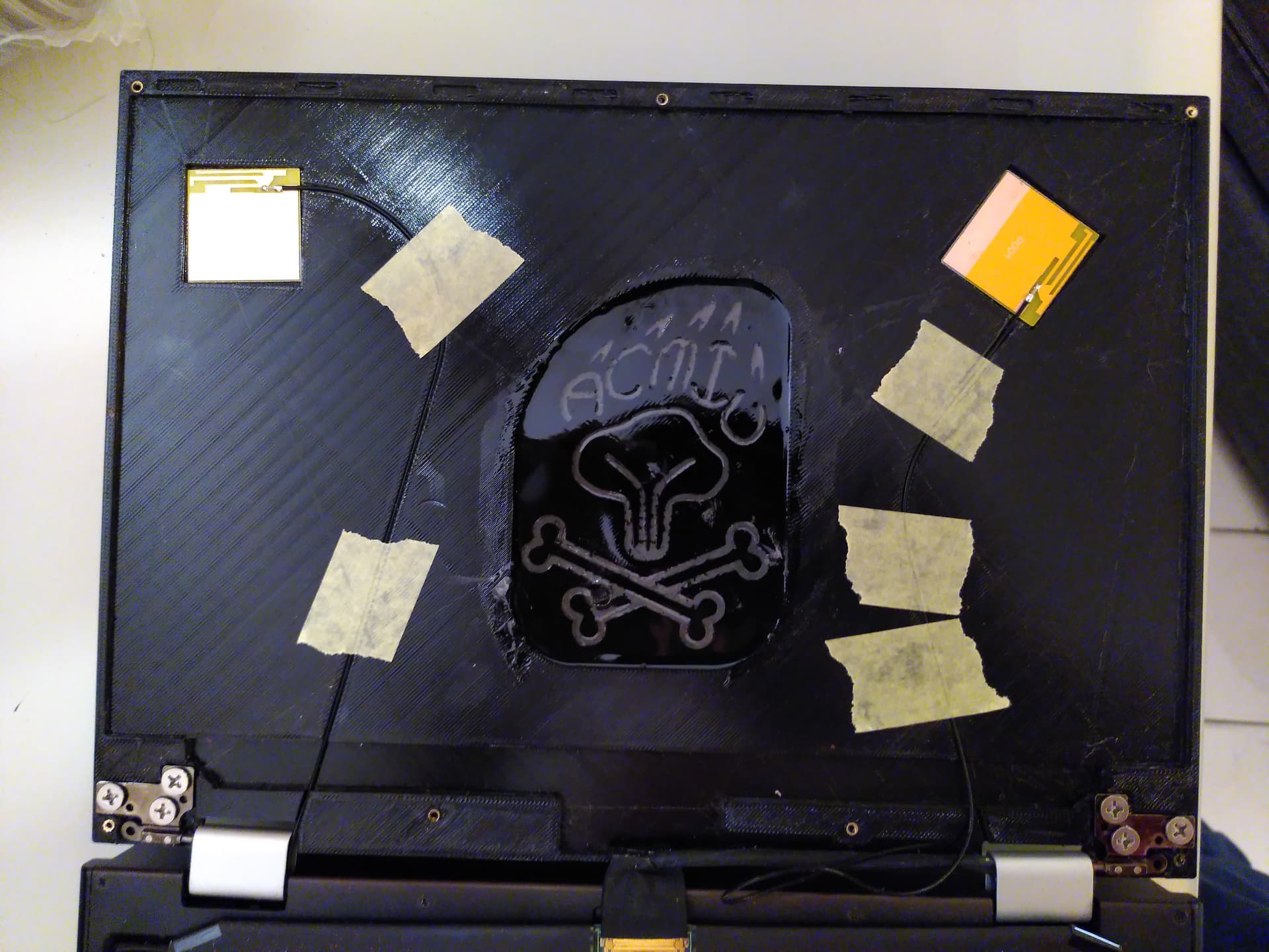
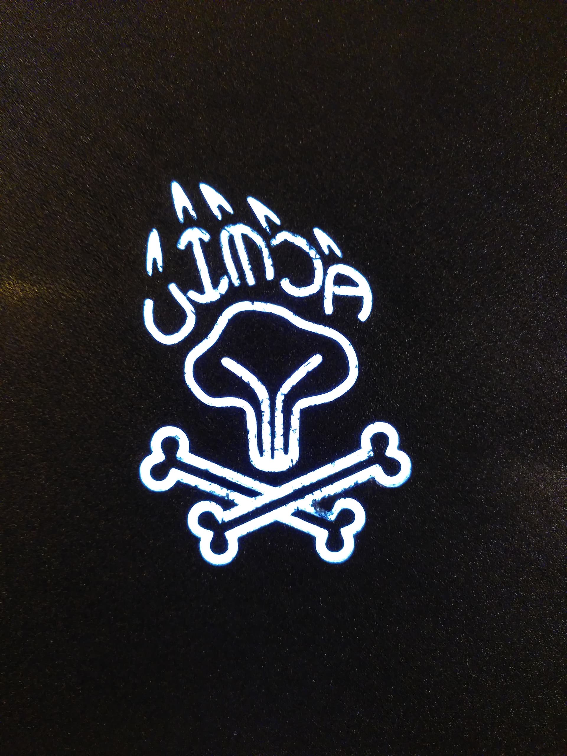
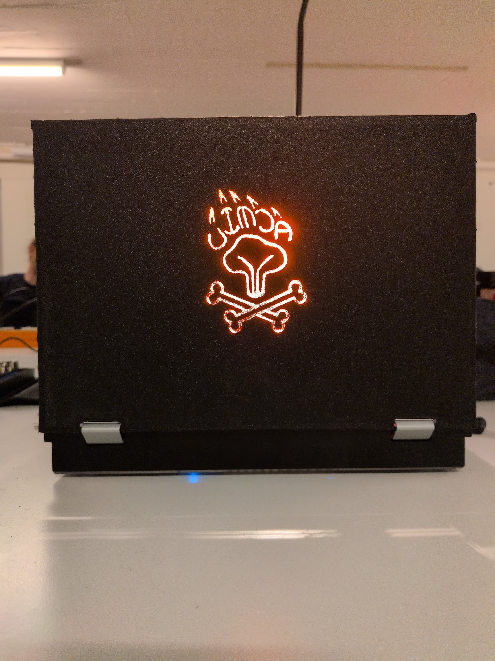
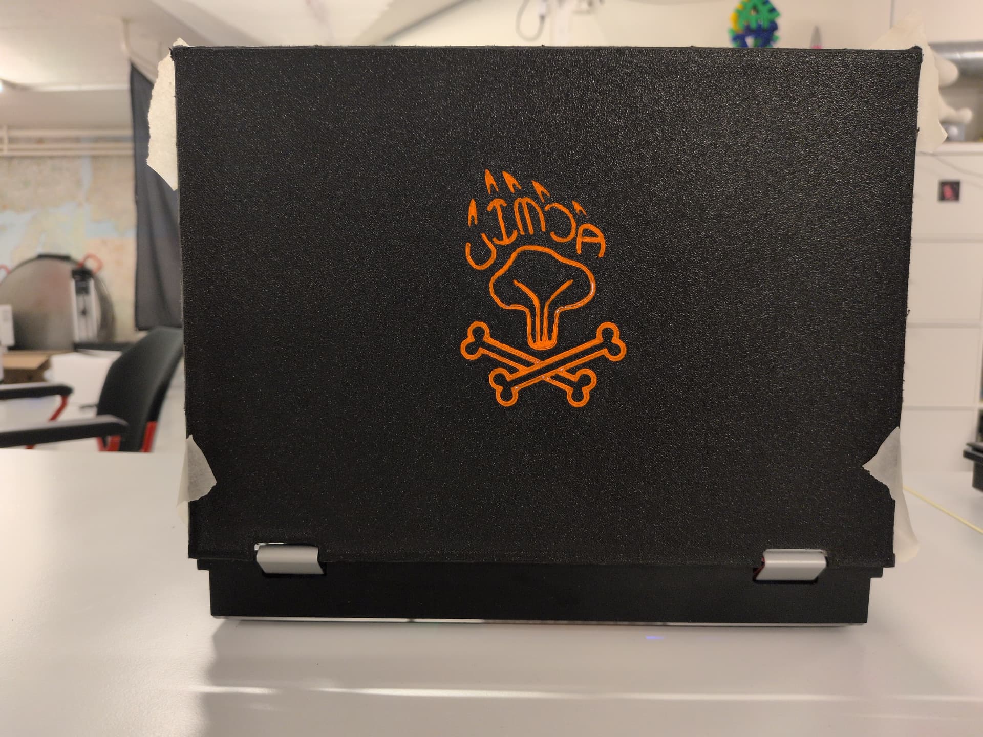
I used orange rather than black for debugging purposes. One side effect of that is that the backlight from the LCD shines through the back of the lid :smiley:

For my next revision I plan on adding space for Wifi antennas. I’ve had quite some problems with bad reception on the reform and since I’m printing plastic, I might as well take advantage of it. I’ll also want to remove more of the weight optimizations to make it more stable.

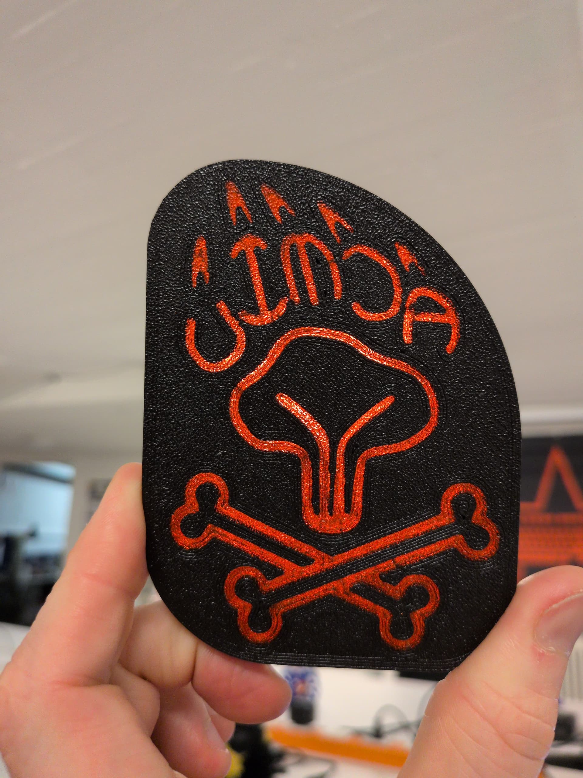
The end goal is to have a custom lid with my own logo of choice. But I am not sure as of yet how I’ll make the final model. I might attempt to print it at a higher resolution and with 100% infill, or I might get it made at shapeways. But that is a problem for future me, first I’ll do some more tinkering and print a couple more prototypes :wink:

16 Likes

Very cool! I love the enclosure myself so I wont be doing something similar, but I do like how making your own lid gives you all kinds of customization options! Thanks for sharing!

1 Like

This is really cool. I wonder if I could hide my 8db wifi antennas in something like that. I only know how to use OpenSCAD, so I’d have to re-model the lid in it, but… might be worth a try?

2 Likes

very nice :clap: … I dig the mixing of black with some touch of color … looking forward to the final version

1 Like

Love it! Very cool. This is the kind of post I’ve been waiting for!

1 Like

I have finally printed a new and improved version of the lid! It’s main feature is that it now has room for W-LAN antennas.


The last print was pretty good and I ended up using it for a while. But it was too flexible. When I pressed on the lid, it would bend inward and touch the panel. Eventually I got concerned and stopped using it.

To mitigate this, I enforced the model in several places by removing a bunch of empty space. I also printed with 100% infill and 0.1mm layer height this time around. Over all I am happy with the result. The print looks a lot better and is more sturdy.

Since the last print, I also made several changes to the 3D printer in the hope of improving print quality, although with limited success.

I also got a set of specialized soldering iron tips to help with inserting the brass thread inserts. This worked great.

Having the W-LAN antennas in the lid makes a huge difference. In a series of before / after measurements I found the reception improved by 7 to 10 decibel. If you’re interested, the antennas I used are the ones here.

Unfortunately I forgot to draw a channel for them from the left hinge which is why I ended up having to file one out of the print :sweat_smile:

The 3D model I used was modified from the the .step file in the upstream MNT repository using FreeCAD. You can find all the different versions in my Git repository here: Niklaus Hofer / mnt reform 2 laptop lid · GitLab

Modifying the .step file in FreeCAD is a bit like editing a PDF file in Libre Office - it works and the result looks OK, but the state in between is cumbersome and rather ugly.

Because of this I have now started re-drawing the model from scratch in FreeCAD, but these efforts are on-going.

Note that I have a beta model of the MNT Reform which has a different lid design. The from scratch re-draw will be of the production model. This should be better suited for 3D printing anyway since the cut-out for the panel is less deep, resulting in a more sturdy print. But I have yet to convince @minute to sell me a production bezzel to match the production lid… :wink:

4 Likes

I have finally printed what should be another prototype, but will probably end up being the final lid made for this laptop.

Yes, you are seeing correctly. This one DOES have an illuminated logo! More on that further down.

Other than that there have been some additional changes since the last design; The cables for the Wif-antennas have been re-routed and the entire panel has been thickened by 1mm in an attempt to make it stiffer. Plus, thinking that this would be the final print, I went with black.

This one was printed upside down, with the outward facing part on the print plate. We made quite some changes to the printer. Most notably the switch from a glass print bed to a PEI covered steel plate. This resulted in this very pretty texture that also helps to hide the print lines.

The panel still has considerable problems. First of all, we are experiencing shrinkage of about 0.4%. This means more than 1mm across the entire width. This means the screws are not placed correctly and the entire thing won’t fit properly, or only when applying some force. One would think that on the 4th or 5th print I would have accounted for that, but…

Also the printer had quite a bit of stringing and oozing, requiring rather more post-processing than I am happy with. Someone ™ decided to switch filament supplier and slicer at the last moment m( Particularly, it oozed into the logo quite a lot. It looks quite nasty :frowning:

We couldn’t really remove those bits before pouring the resin because how how we did that. We poured the resin while the print was still on the heated print bed. This solves the problem of sealing the pour plus the hope was that the resin would end up with the same texture as the print, leading to a more uniform look. Prior testing showed that this is problematic:

The resin sticks to the PEI sheet too strongly. In our test print parts of the resin ripped out of the print when separating it from the plate with force.

To help with that, we paused the print after the first layer and brushed some silicon grease onto the plate as a sort of release agent. This however, caused additional problems with grease getting to places it was not supposed to. Plus it only sort of worked.

Now, where does that leave us? I now have a back plate that I’m happy to show off. Tomorrow my new mnt reform 2 is supposed to arrive. This one will be a production model, so my old lids won’t fit.

We are still working on re-drawing the lid from scratch in FreeCAD. Working off the .step models is hell.

We are already working on solutions to the resin vs PEI problem. Right now a model is curing which is using some MagiGoo as interface material. Let’s hope this works. I would really like to do another print before revision, so I can show off my new reform with a custom laptop lid!

4 Likes

Wow, this is super impressive!

I’m interested in the long-term success of the wifi antenna cables, given that they are repeatedly twisted at the lid.

Is there a reason for the antenna placement you chose?

I’m also a bit confused because in your initial post you said you printed it for the MNT Reform 2 but it’s actually one of the first generation?

Are you sure that there is no better source for the .step files? Did you ask Lukas about that? I might misremember but I think they were in a directory different from where the .step files can be found.

I love the idea of using transparent resin for the logo.

Amazing stuff!

For me the tank like build of the Reform is one of my main pros of it. BUT, this is really cool. Thanks for sharing!

1 Like

I’ve been using them in the previous iteration for almost 10 months by now and haven’t noticed any issues as of yet. It’s not like I’m using my reform every day though. But a couple of times a week for sure.

I have described the reasons for moving the antennas into the lid and the results I’ve seen in a previous posting.

As for how I chose the exact placement inside the lid, there is not much to it. I just placed them wherever. That said, I’ve heard that Wifi antennas work better if they are not all parallel to each other. But I don’t really know what that means. This is why I decided to rotate one of them 45°. Maybe 90° would be better though?

As you can probably tell, my knowledge of radio technology is very basic. I just sort of winged it.

Sorry about the confusion. No, I don’t have a first generation reform. But what I do have is an early prototype (pre-crowdfunding) of the reform 2. Mechanically it is largely the same as the final product. But the lid has been changed quite a bit.

In fact I think that the final design is better suited for what I’m trying to do, as the LCD panel is not sunk in quite as far, leaving more material, improving stiffness when working with plastics.

MNT research does in fact publish the the Fusion 360 sources for the case. Unfortunately there seems to be no better way to import from Fusion 360 to FreeCAD than using .step.

It’s not a huge problem though and drawing from scratch is teaching me a lot about CAD that otherwise I would not be learning.

1 Like