I added an active cooling fan to my mnt reform

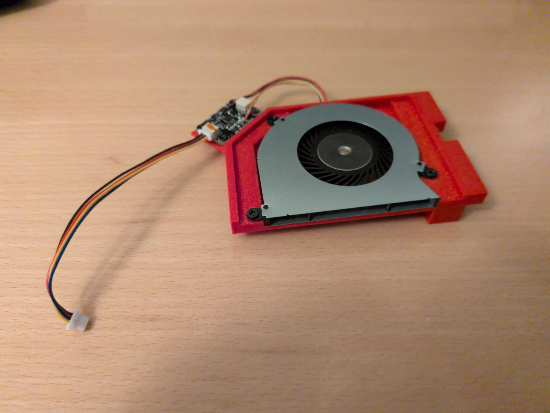
I have added an active cooling fan to my mnt reform2!

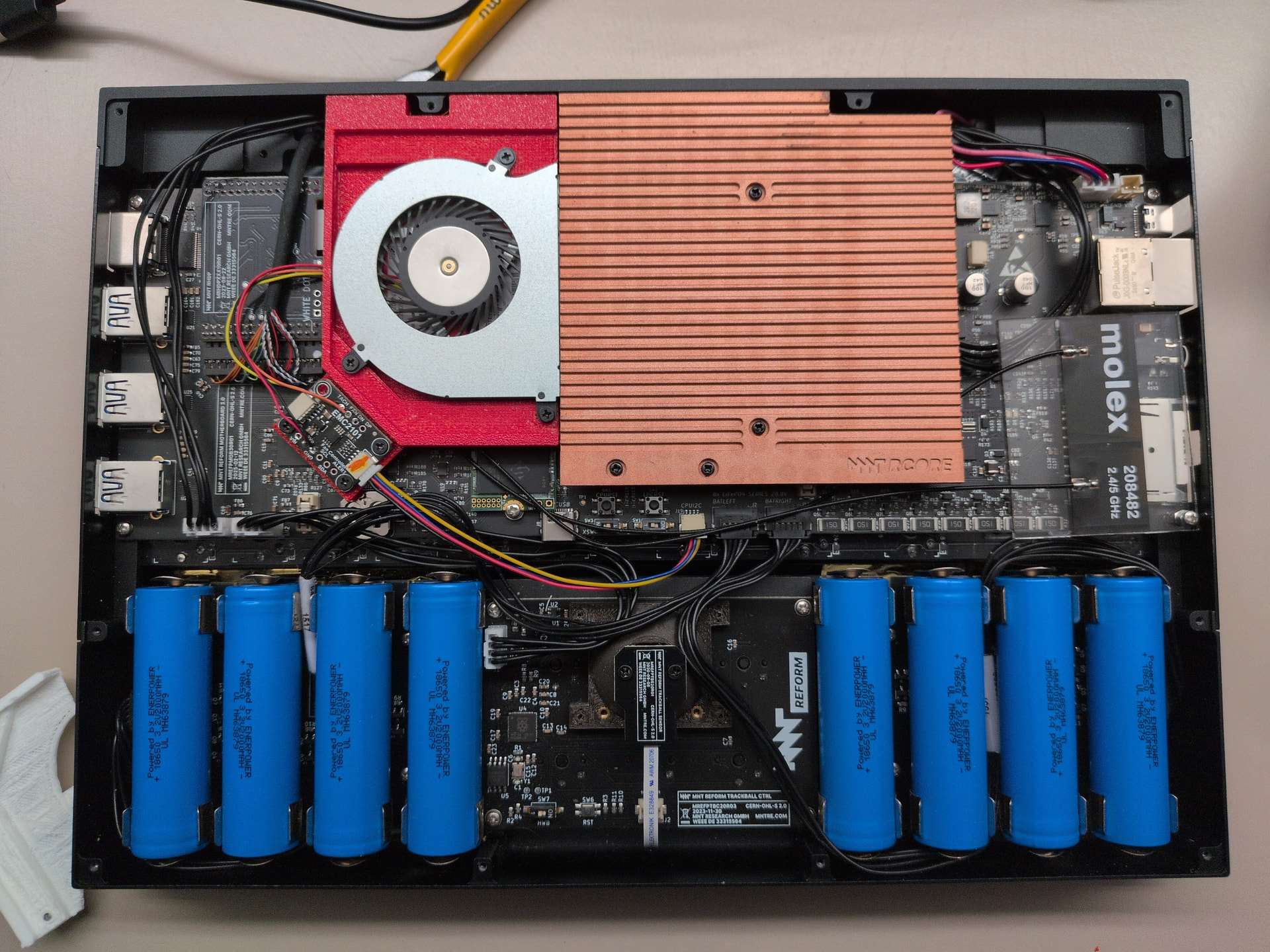
And you can do the same. Get the 3D model and details on the components used here: Sign in · GitLab

This is using a 3D printed frame to hold the fan in place. The fan itself is an off the shelve unit. It is controlled via I2C PWM controller. Please note that this requires a 3.0 motherboard.

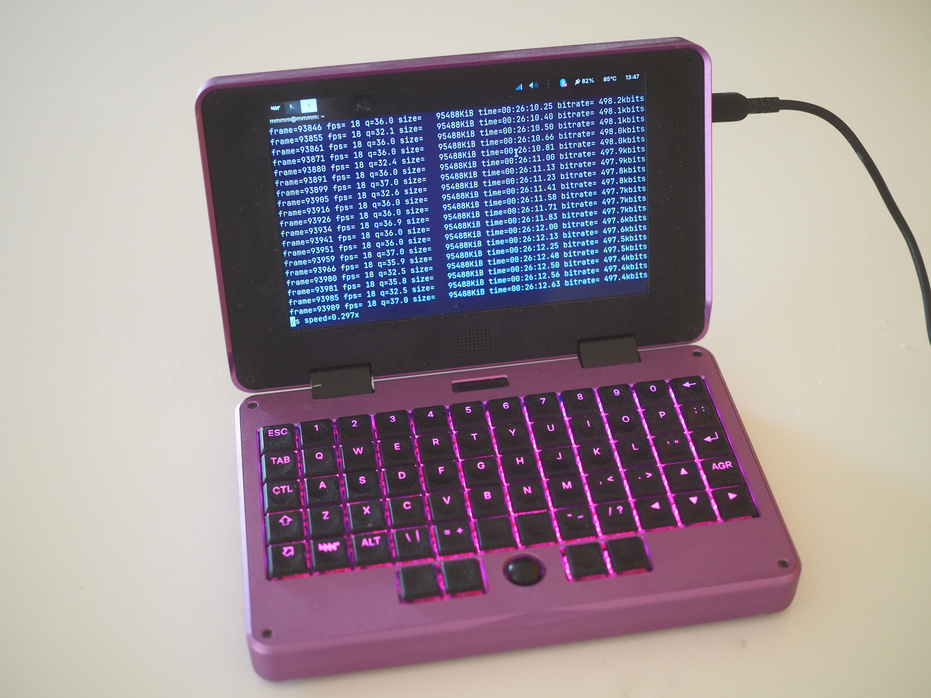
At the moment I use i2cset to manually set the fan speed. I have a small bash script that runs lm-sensors in a loop and then uses i2set to set the fan speed accordingly. It’s very basic though, you can probably do a better job yourself.

I have been wanting to do this for a while now. Originally, I was planning to connect the fan to the Hack the planet / GPIO Pins. But when I learned these were connected to the system controller and not actually the CPU, I gave up on that idea. Sure that could be done, but although I remember enjoying writing embedded C code at uni, I haven’t done any serious programming for almost 10 years and this seemed like a rather daunting project. Even more so because the system controller would need to communicate with the OS to get CPU temps anyhow. So when mnt announced the 3.0 motherboard with CPU connected I2C, I was only too happy to wait for that.

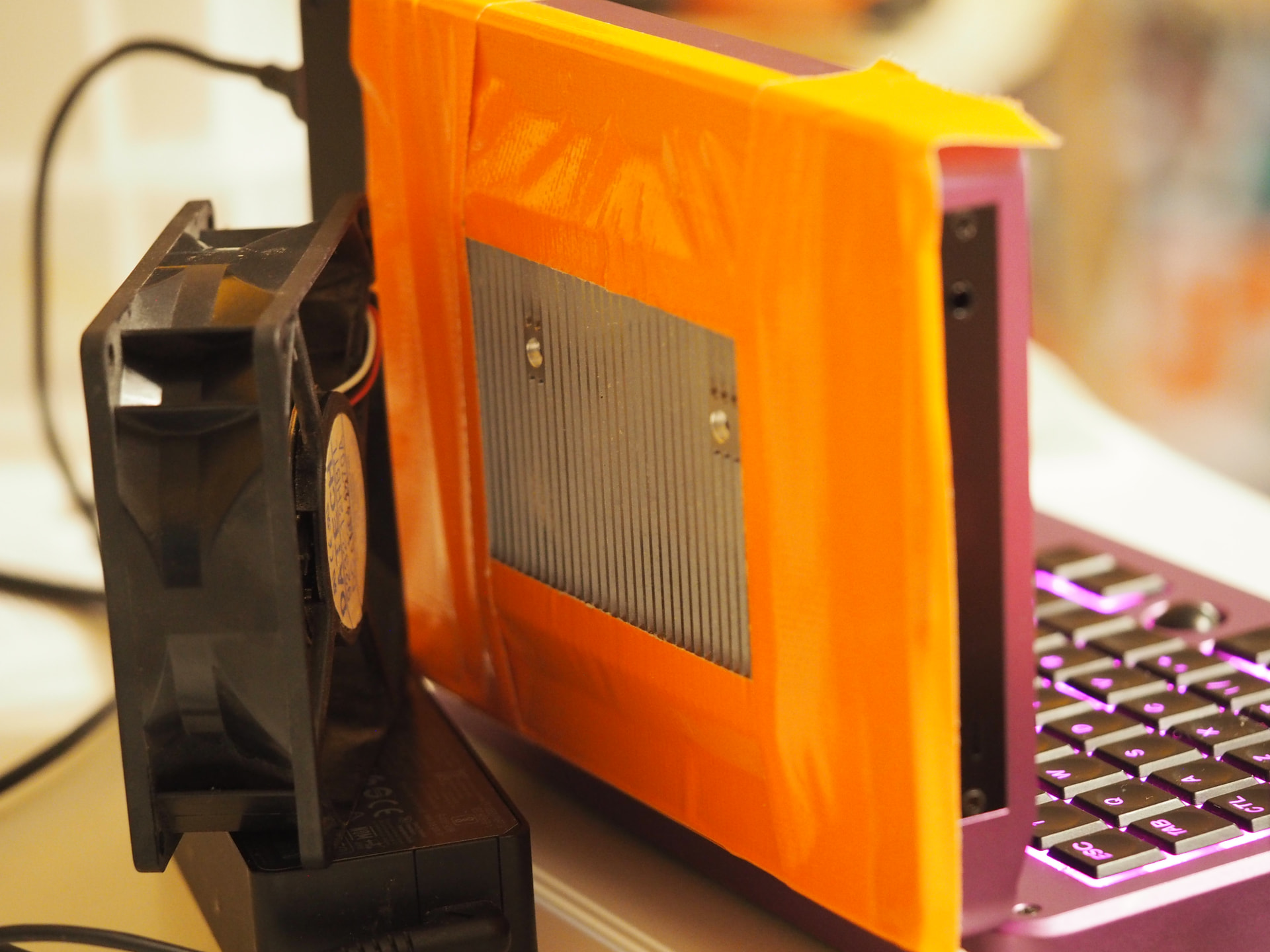
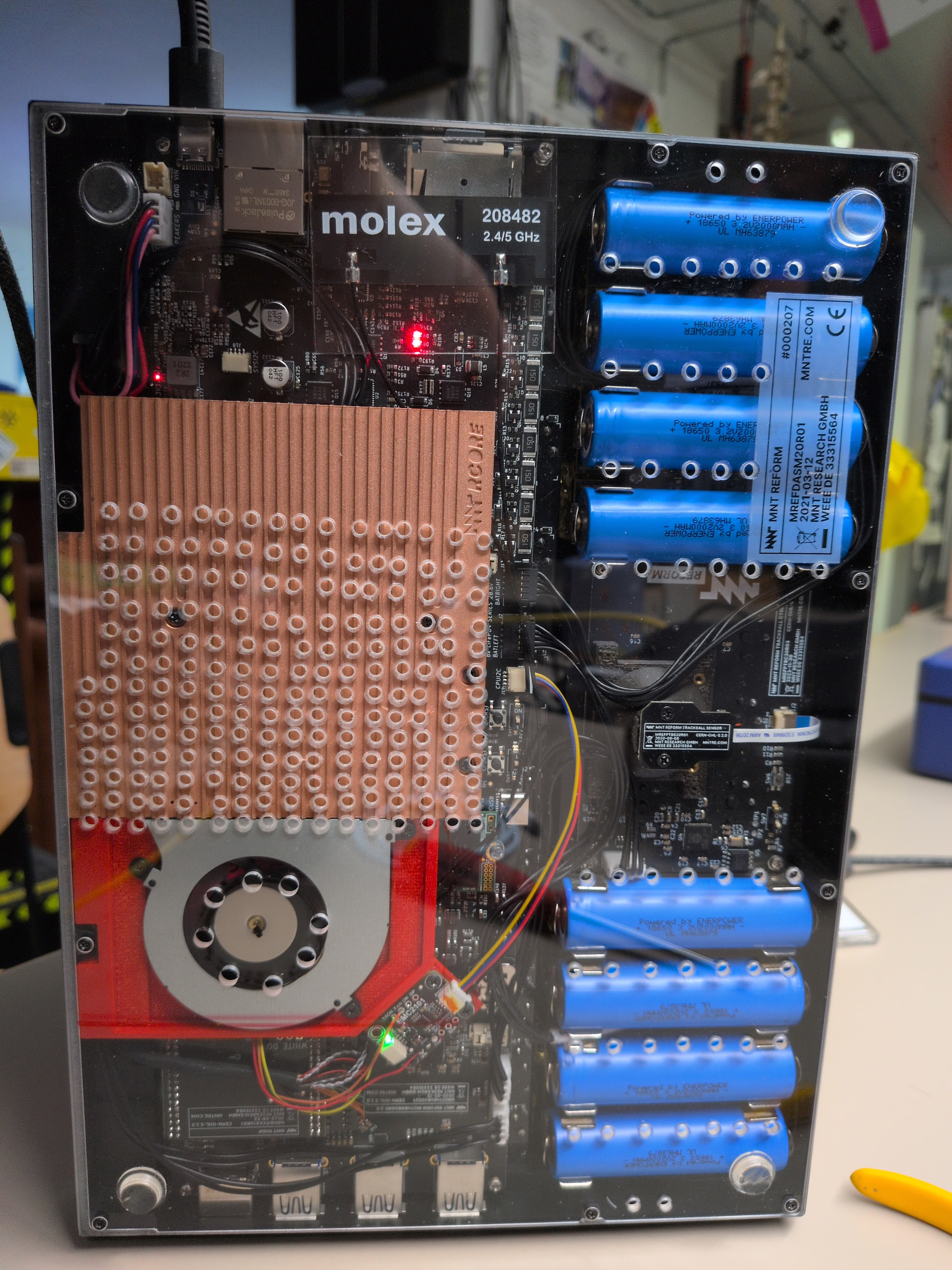
Most of the holes in the bottom plate have been drilled long before this. Until now, I just had an external fan blow some air at the bottom of the laptop when I was compiling for a long time. I’ll probably get a new bottom plate and drill new holes in different positions to “optimize” for this new set-up.

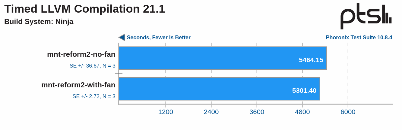
I haven’t really run any benchmarks as of yet. But I have toyed around with it a bit. During this, I have seen the CPU temperature fall by up to 15°C when turning on the fan under load, which is quite good I guess. The fan does get quire noisy though.

The fan is fully wired up to the PWM controller, including the power. I thiiink that is OK, but really I’m not qualified to say. We tried to jam the power wires into one of the USB connectors first, but that was so flaky and we gave up on that eventually.

7 Likes

Incredible work! Thanks for making everything available on the GitLab :slight_smile:

2 Likes

Over in the fediverse, @josch asked me to run some benchmarks. And so I did. Or one at least:

tl;dr: It only matters on long lasting loads. And even then the difference is negligible. But it helps to keep the device and components cool.

I ran a compile benchmark since that, running Gentoo, is the typical load I have on my laptop. The heat sink can soak up quite a bit of heat, so any difference will only show up on long runs.

For the test without the fan, I removed the fan entirely and taped off the holes in the bottom plate to get as close to stock as possible. The tests ran three times in direct succession. The laptop started out at about 40°C and it took about an hour to completely heat soak. After that it was 80°C and the CPU started throttling. Temperatures would fluctuate between 78°C and 83°C and depending on the exact temperatures, the CPU would some times throttle and other times it would not.

For the second run, I re-installed the fan and removed the tape. The system would get about 60°C with the fan running at 75% speed. The CPU did not throttle and you can see this in the results that are a tad bit better.

For me though, this is absolutely worth it. The device is more pleasant to touch and I feel better knowing it is not terribly hot.

Funny thing, at first I tried to run the test with the fan off but still installed. But that did not go well at all. When writing the results for the first test run, the SSD controller overheated and shut down, rendering the system useless until a reboot. That is, I guess, a thing - the mounting bracket for the fan covers the Wifi card and SSD. But when the fan is running, it also draws air over them and over all, the SSD staid cooler with the fan installed and running than it did without the fan installed at all. Without the fan installed, it spiked to over 80°C at times, but it held out well throughout the several hours of testing, so that’s good.

The fan, btw, can be removed easily. It’s a discrete unit that only needs a single plug. That was not a design goal, it just worked out that way.

5 Likes

I love the setup, and this heatsink is massive. Probably the exit vents should be moved further away from the fan. This would allow the air cool more surface before exiting.

I’m yet to receive my unit, but already interested into the RK3588 cooling project you’ve been doing.

1 Like

I was also wondering how large in practice the actual benefit is over preventing RK3588 from throttling, so I built this test setup with the RK3588 Pocket Reform:

Yes, this is just “Pocket Reform on desk” but I had to create some sort of setup which was a more or less realistic scenario. Clearly my room temperature and general ventilation will also play a big role so all of this is just to have some ball park numbers.

To benchmark, I encoded a video with ffmpeg on all cores. With the setup above, this took 3.89 hours.

To prevent throttling I put an 80 mm cooler behind the Pocket Reform, making it blow on the back of the display. Unfortunately this was not enough to prevent throttling according to /sys/class/thermal/cooling_device*/cur_state which will start the throttling at around 81 °C and make sure it nevre goes beyond 85 °C. So to help cooling even more, I taped the LS1028A heatsink to the back of the pocket display:

With that setup, temperatures stay at around 70 °C, so no throttling will happen even at full load. With that setup, the same video encodes in 3.27 hours. That’s 15% faster compared to encoding the video without active cooling. This difference is significant but my personal takeaway is, that it’s not worth the hassle for me.

4 Likes

This is super interesting for doing things in warm setting though! I imagine doing something on an outdoor stage in summer time.

What could actually be a very cool (pun intended) project would be an alternative top / backplate for the Pocket that would include heatsink and fan all in one and that would be easy enough to screw on and off that you could mount it in summer, and unmount it when temperatures were cooling down.

Edit: I could even imagine multiple sizes:

  • Normal - For normal use (stock back)
  • Extended - Medium fan for big tasks in normal temp, or normal task in high temp.
  • Supersized - Big strong heatsink and fan for keeping the cou cool even in the toughest situations!

I’ve owned a classic Reform since 2021 and I’ve opened and closed the bottom acrylic a lot since then. I have not made good experiences with screwing M2 steel screws into aluminum. Several of the 10 threads are worn out and the screws fall off. Right now, my bottom acrylic is held by only four screws.

Maybe instead of using screws an alternative backplate would contain a layer made of some ferromagnetic material. Is that easily possible? If yes, a heatsink with our without fan could be clipped on and off using magnets.

1 Like

I thought about some sort of magnetic back but I’m not sure it will work without serious chassis mods. So I’ve been trying to print some plugs that would friction fit into the screw holes. Getting okay results with PLA, but not getting consistent print sizes. I’m not have any success with printing them in TPU, which seems like the more appropriate material for such a task, it just seems too fine. Ordered a smaller nozzle to see if that would help improve PLA consistency or TPU.

This is what I’ve modeled up so far in openSCAD

pin();
module pin() {
// Head
cylinder(d=3.5, h=1.5, center=false, $fn=30);
// Shaft
translate([0, 0, 1.5])
    cylinder(d=1.66, h=5, center=false, $fn=30)}
1 Like