I re-installed the LS1028A module in my reform and noticed that USB was broken again during boot. I had installed a fresh Debian unstable image to a SD card.
Turns out that the reform-hw-setup script was failing because gpioset is used in the reform-hw-setup script and that tool has changed behaviour in recent releases.
Previously the chip name was the implicit first parameter and the default mode operation was to change the state and exit. Now the chip has to be set explicitly with the -c flag and the tool keeps running while a certain state is set and will unassert the state on exit.
Diff:
$ diff -u reform-hw-setup*
--- reform-hw-setup	2025-05-19 08:56:43.033026307 +0200
+++ reform-hw-setup-mod	2025-05-19 09:07:16.647020433 +0200
@@ -153,13 +153,14 @@
   "MNT Reform 2 with LS1028A Module")
     # Workaround for a DWC3 USB Controller regression

-    # Assert USB hub reset
-    gpioset 2 13=0
+    # Assert USB hub reset while gpioset command is running.
+    gpioset -c 2 -l 13=active &
+    GPIOSET_PID=$!
     # Reload DWC3 module
     rmmod dwc3
     modprobe dwc3
-    # Deassert USB hub reset
-    gpioset 2 13=1
+    # Deassert USB hub reset by stopping gpioset command.
+    kill $GPIOSET_PID

     # Select "ondemand" CPU frequency scaling governor
     echo ondemand >/sys/devices/system/cpu/cpufreq/policy0/scaling_governor
I’ll send a patch once my account on source.mnt.re is approved.
Note: This does not reliably enable USB during boot, but it seems to work more than half the time. My reform also does not seem to reliably shut down, but I haven’t debugged this yet.
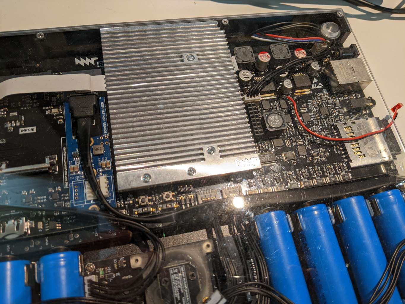
Since the LS1028A has SATA on the M.2 port, I got myself a board to break out a SATA connector (NGFF1ST-N02) and soldered cables to C125 (30V) and C65 (GND) for power (MB rev 2.0, the ibom was very helpful).
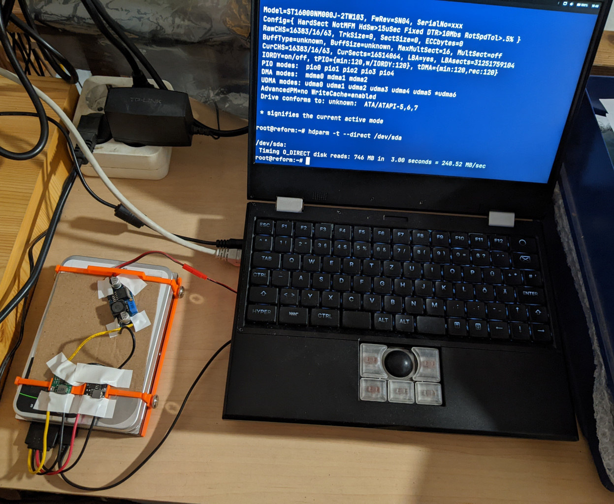
Power connects via a JST RCY connector to a first DC-DC converter board which drops 30V to ~16V. I used further DC-DC converters for 5V and 12V and an old Molex to SATA converter cable to actually power the HDD. Along with a normal SATA cable snaking out the side of the reform, this works well for powering a 3.5" HDD with the battery monitor showing about half an Amp of power usage. A 3D printed harness keeps things in place, but the setup is unlikely to be EMI compliant.
Edit: The first voltage converter is required because the other converters I used have a maximum of 28V input voltage.
(This replaces a similar setup with an old laptop mainboard where I tapped into the 19V input power.)
Soldering to the reform is very difficult, likely due to large power/ground planes acting as heat sinks. I don’t have a rework station to heat the full board to 150°C, fortunately soldering to small capacitors worked. I wonder if a hot air soldering gun would also work to heat up the board to sufficient temperature before trying to use a soldering iron.