Kickstart, AmigaOS Versions: 3.2.1 47.102, AOS 3.2.1
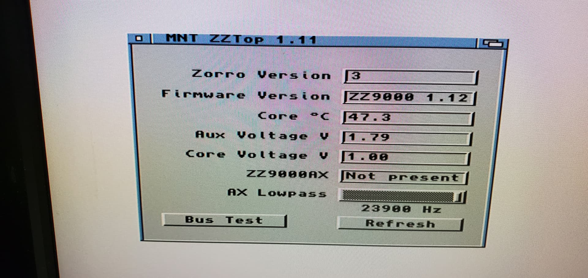
ZZ9000 Firmware version: 1.12
ZZ9000 Driver version: 1.12
Monitor model: Dell u2410-f
Other Zorro cards: none
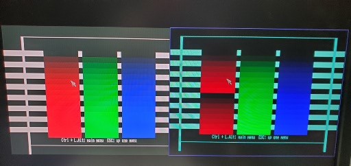
RGB from db23 left, pass thru from hdmi right. Above Suggests problem with red portion of RGB?
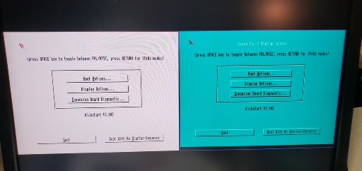
Green/Cyan tinge on anything white, tried different CX cable, other video slot (1st CX moved,then ZZ, then both), disconnected db23, tried different monitors, different hdmi cable, changed MB jumper off of “sync on green”, always same result. RTG video looks great. Changed FW to v1.9 (did not change driver install to match) same result. Verified Z3 1.12 Boot.bin What else to try? Bad CX card? Appreciate any guidance…
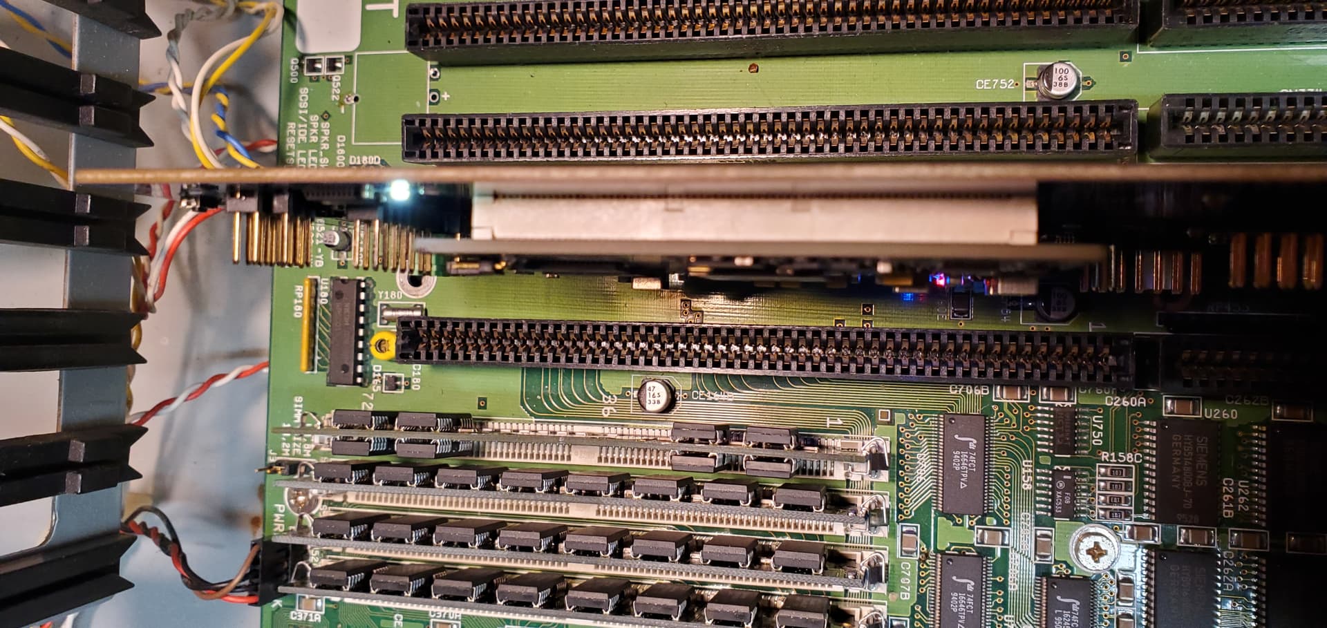
Hi, sorry for the trouble. This is usually some loose connection. Can you try (with device turned off!) to firmly press on all four corners of the ZYNQ module so it is fit snugly?
Hi there, this will start out a bit odd, but hopefully might make sense in the end.
I had a very similar issue with an A1200 some time in the past, what is relevance to ZZ9000 you ask? It turned out that there was a motherboard issues (broken SMD resistor as it turned out) which had killed the high-bit of the red colour channel, thus there were only 128 “shades of red” that would repeat (i.e. no high-bit, so had red levels from 0-127 and if the high-bit was “set”, it was another 0-127 rather than 128-255).
So, what I’m wondering is if the path to the video slot(s) is damaged and the path to the RGB port is fine? Might be worth checking the red traces with a multimeter for continuity if possible (while the machine is off obviously).
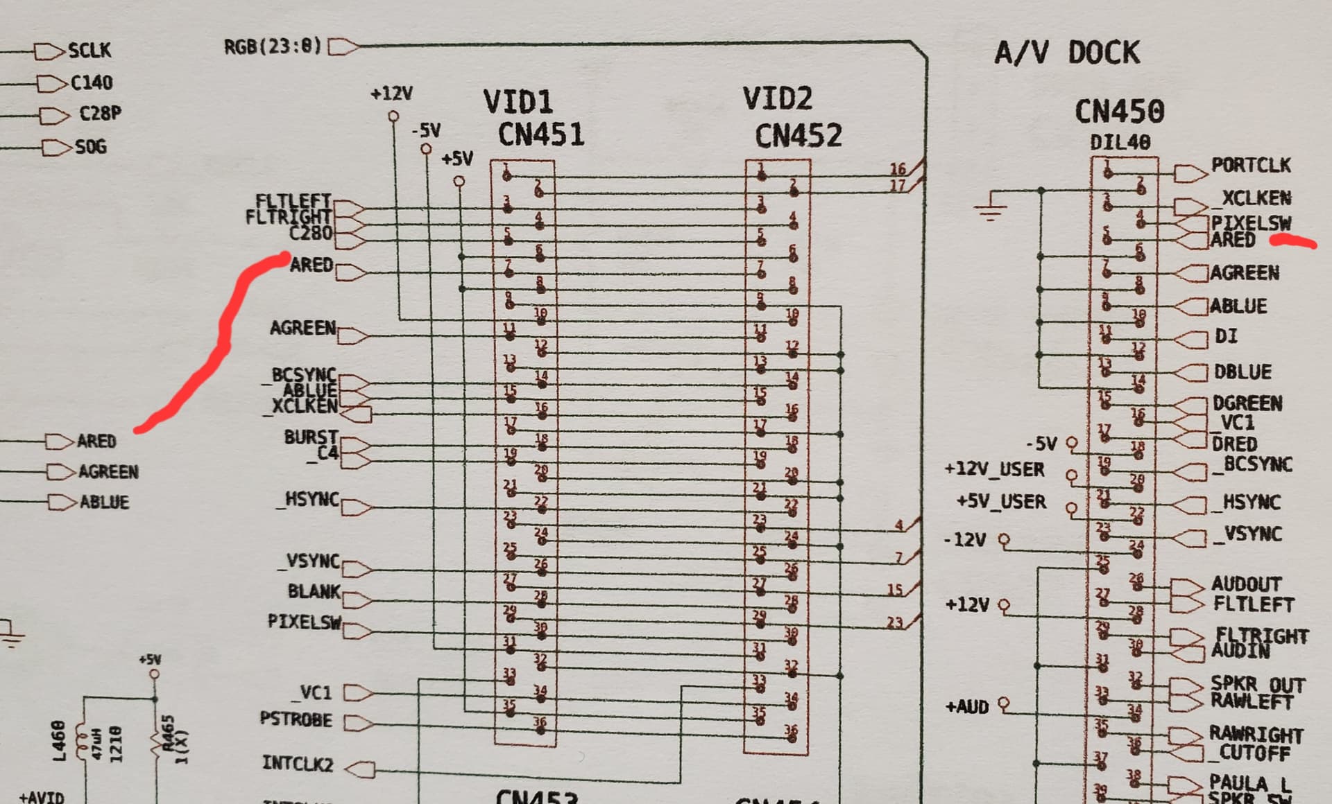
Yes, that seems like a possible cause, I have examined the schematic and there does not appear to be any components between the ared source (DAC) and the video output to the RGB DB23 connector, which is also the case for ared going to POS 7 of the video slots CN451 & CN452. To me this indicates it may be a trace to the slots that is bad?
Or… As MNT asked above, there is a loss of the signal on the ZZ9000 itself, but the seating of the ZYNQ module is solid and does not appear to be the issue… I appreciate the advice.
Thuman
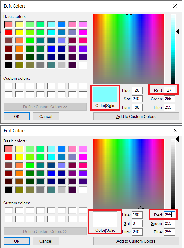
ZYNQ module is solidly mounted, it looks like the red signal from the ZZ9000 is missing the hi bit? Values above 127 are going back to 0 thru 127 instead of 128 thru 255, making white show as cyan?
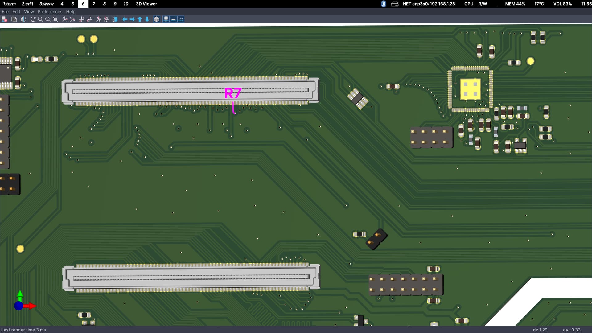
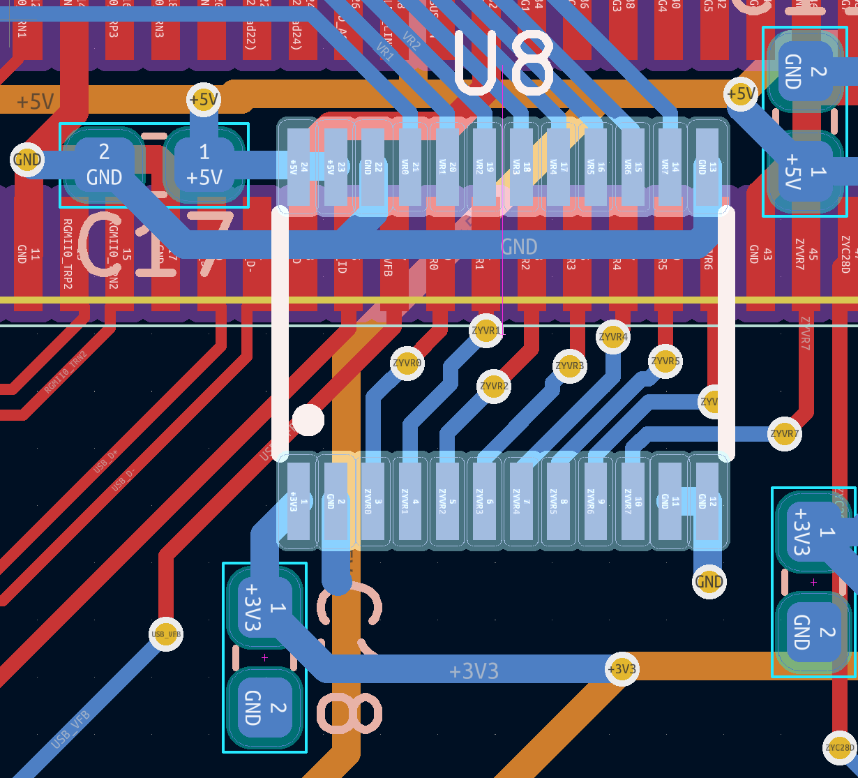
I’ve made some annotations so you can check (take a close look at pins and beep with multimeter) all the relevant points in the signal path of red bit 7:
Signal comes from the video slot connector here and enters U8 pin 14 for level shifting:
Hi Lukas,
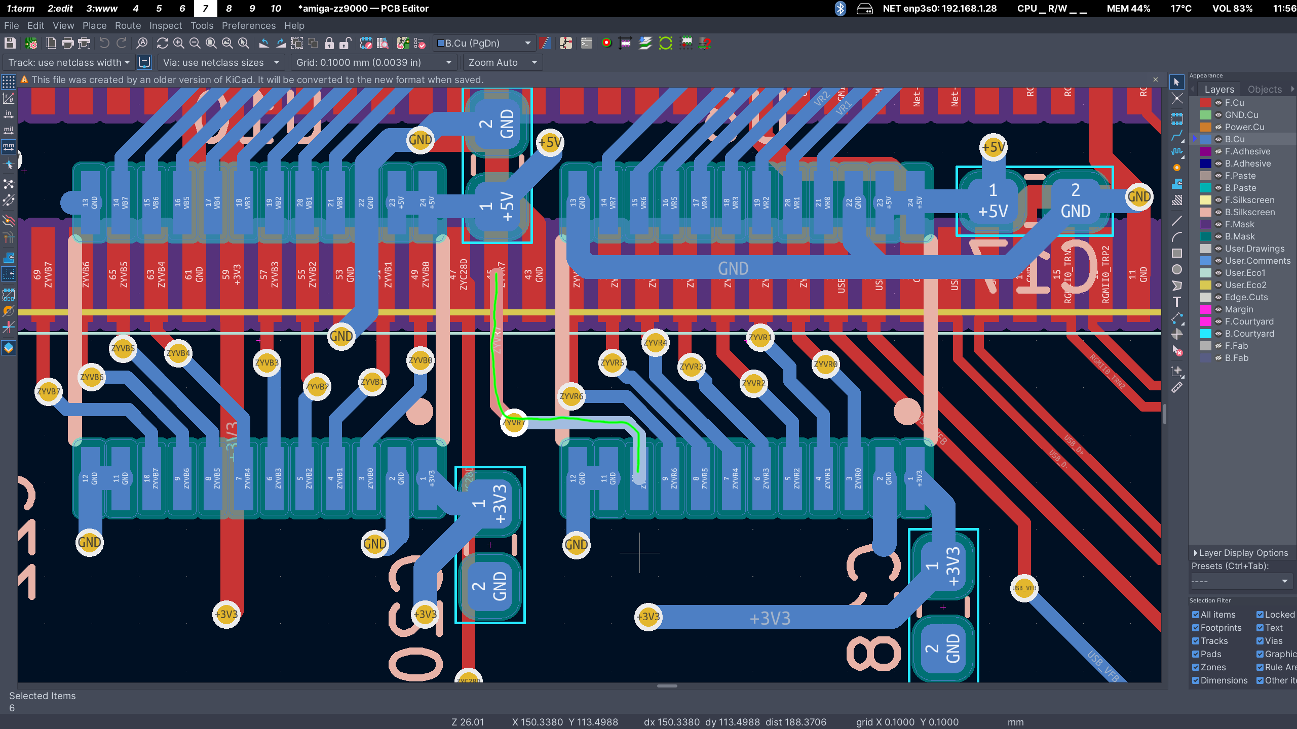
I finally had a chance to do a continuity check between Pin21 of J9 SlotIDC_OUT and Pin 14 of U8, this checked good with beep test, and also Pin 10 of U8 to Pin 45 of U12, the top ZYNQ module socket, this also checks good.
Since I was not sure where to check the signal path further on the ZYNQ module, I decided to verify continuity further upstream from the J9 IDC connector, all the way back up to the source of VR7 (RGB23). Everything I checked continuity on shows good, back through the 34 pin ribbon cable to J8 SlotIDC_In Pin21, through the VS2 connector on the CX board Pin 29, and through the VID2 CN452 connector on the 4000T.
I then checked continuity between CN452 Pin 29 back to U457 through the RGB(23:0) bus, RGB23 connected to the R457A 100ohm resistor and also the RP457 1Kohm resistor to gnd. All of this checks good to U457 Pin 2, including the connection back around from R457A to U457 Pin 32. The resistance readings all are within tolerance. I then continued on the upstream side of U457 Pin 47 to the Video DAC U460 Pin 35 (R7 In), and then up the LRGB(23:0) bus to the U450 LISA chip through R450H 68ohm resistor. I believe that since the ARED signal from the Video DAC looks correct coming through the 23pin RGB Output, the R7 bit must at least be making it to the input of the U460 DAC.
Is there a way to verify the logic signal levels coming out of U8 on the ZZ going to the ZYNQ module, or perhaps upstream from there on the 4KT side using a logic probe?
Btw - this is a very similar issue that I am seeing and it’s perplexing! I did manage to find some bad solder joints on the PCB at the slot, and the RPs. I fixed all those up, and while it definitely improved things, I now have a ATK RGB test that looks like that. I too checked all resistors that hang off those RGB lines and everything appears good.
The only other thing I guess I could try is cleaning the slot with some IPA and a toothbrush.
I thought the same, that it must be a connection issue, but after some troubleshooting I found that the high bit of the red digital signal was not coming to the ZZ9000 from my motherboard. I verified this by tracing the signal from the video slot back upstream to the bus transceiver chip U457 (A4000T MB) which has the red bit R7 coming into the chip, but nothing coming out to the video slot. I used both a Logic probe and an oscilloscope to verify signal levels. I have the new chip to replace U457 ( about $10) but have not made the repair yet, I need to practice my SMD soldering skills a bit before I take that on… I hope you find your problem is something simpler…
Ok, I fixed my issue. Interestingly, it was R7 that had issues for me too. Although I was seeing the transceiver driving the right thing; the only thing between that and the slot was a 47ohm resistor (R455A) on the underside of the motherboard. All the other resistors there were reading 47ohms, except that one (it was floating wildly!). Replaced it with a new 47ohm and now it’s working perfectly. Thanks for kicking off this thread, it got me pointing in the right direction.
Glad to hear you got yours resolved. Curious that is was R7 for you too… I pulled my board and checked that resistor and it checked good but I think i will check it again before going all-in on the bus transceiver chip swap out… That R7 signal swings back around to another input on the same chip after the resistor and it messes with the resistance reading when still in circuit… at least on the 4000T.