This machine charges super fast, but it also really loves to overload power supplies, leading to poor efficiency with solar power and tripping protection even on USB-C chargers rated as high as 65W, depending on a few factors.
The other downside is that it’s less than ideal for battery longevity.
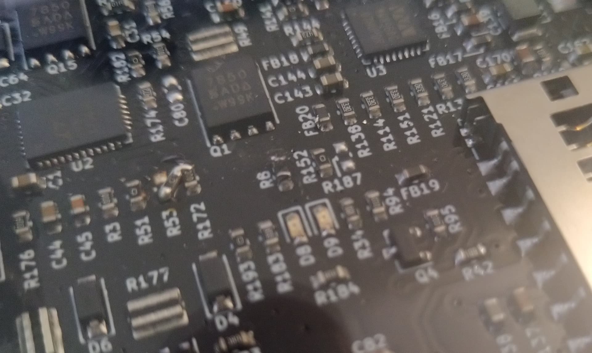
A while ago I recall some chatter on IRC about changing the value of R8 (LTC4020 ILIMIT) to fix the Reform MB 2.x’s excessive charging habit.
Values for for R8:
Reform MB 2.0 schematic has 100K
Reform MB 2.5 schematic has 100K
Reform MB 3.0 schematic has 7.15K
Has anyone changed this on a 2.x motherboard? Bodging a 8K in parallel with the 100K already on the board gets pretty close to the value used on MB 3.0.
I intended on doing this to mine, but haven’t had the chance to tear it all down.
I have motherboard 2.5 with A311D so let me present my experiences with power and charging. I haven’t changed hardware but upgraded firmware few times.
I received new hardware in February 2024, and from the very beginning had problems with charging. After some discussion on this forum (I was not the only one with those problems) Lukas prepared new version on branch mb25-charge-delay of Reform / reform · GitLab It helped situation a bit - I was able to use 24V charger. 20V USB-C converters from Ada Fruit (mentioned elsewhere on this forum) were not working, but 12V was - although it was providing less current during charging (around -0.7A instead of -1.6 or so with 24V). 20V charger from another laptop was mostly working - except when batteries were below 50% and I was using it. Then it was unable to provide requested power.
Some time ago I noticed that branch was merged around October/November to master. I compiled it and flashed my laptop. OLED shows now 20241018. After this change charging behaves much better. I did not take big charger to FOSDEM but only USB-C adapters and was able to use MNT Reform daily without problems. 20V USB-C behaves now a bit like 20V laptop charger from previous paragraph. It can charge MNT Reform reliably when it has 60% charge or more. If less - it sometimes works, sometimes not. When it works, OLED shows up to -1.6A, so similar to 24V. Once I seen slightly over -2A, but was not able to repeat this. 12V works as previously - reliably, but providing less current and laptop heats more when I use it.
In summary - new firmware behaves much better. I still believe it’s too aggressive (I’d prefer slower but more reliable charging), but Lucas started exprimenting with USB-C chargers (I assume for MNT Reform Next) so hopefully we’ll have some fixes in the future. As I do not have experience with electronics nor with low-level programming, I’m abstaining from writing my own code touching power.
I got the parts and added the 8K resistor on top of R8, both together measured 7.4K. Now my Reform with MB2.0 can charge off my USB-C power using 36W without tripping it into over-current protection.
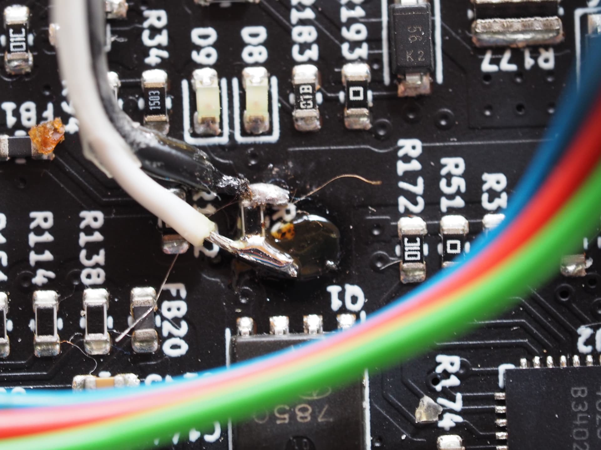
Using the 10k potentiometer I was able to vary ingoing power between 10 W and 60 W. But after a while (no idea what triggered it) the maximum power draw dropped to 32 W. I noticed that there was now a ~4.2 kOhm resistance between pin 25 (the ILimit pin) of the LTC4020. So I cleaned everything up with IPA as best I could but the problem remained. I removed the 100 kOhm SMD resistor to make sure that it was not somehow the culprit but even with that resistor removed, there was still a 4.2 kOhm resistance between the R8 pad to the north and ground (the pad to the south, the photo is upside down compared with the KiCAD schematics):
So the problem was not the SMD resistor. I used magnet wire to install my variable resistor and put everything back together. Now I was able to vary power draw between 10 W and 28 W. Wait, why not 32 W. I measured again and now the resistance between the ILimit pin 25 and ground was down to 3.8 kOhm. Whut?
I have no idea what’s going on here… Charging with 28 W is fine but I’m out of ideas of what to try next to figure out what is going on…
Either there’s a partial short somewhere on the board (conductive flux maybe?), or its internal to the chip. I see some dust and grime in the photo so maybe it’s worth giving the whole thing a good cleaning with isopropyl alcohol and lint-free swabs or cloth.
Parallel resistances add up like this: R = 1/(1/R1+1/R2+…1/Rn), so it’s not surprising that your 10k pot in parallel with whatever is going on on the board would be around 3-4K.
I let the Reform battery die flat and then tried to charge it off a 60W USB-C (PinePower) brick and it still won’t do it.
Connected up to my ham radio supply, it’s pulling 4.2A at 13.8V, so around 58W. With a 20V trigger cable, I’m willing to bet it’d be exceeding the 3A limit with no soft-start, but I can’t tell since my USB-C monitoring device resets when the power supply kills the port.
It’s still lower current than the charge circuit was pulling with the 100K resistor only.
If I have time I’ll do some research and try to build a soft-start with a capacitor on either ILIMIT or RNG/SS.