Here are STEP files with pdf diagrams too:
These appear to be only for the “frame” part of the case and the bezel? The actual PCB plates used on the flat part of the case seem to be here: case-plate-pcbs · main · Reform / MNT Pocket Reform · GitLab
The back plate is defined in the the pref-display-back* KiCAD files.
1 Like
I’ve been able to reproduce @pandora’s findings with my own custom back plate. My testing isn’t so rigorous, but hopefully enough for others looking to do something similar.
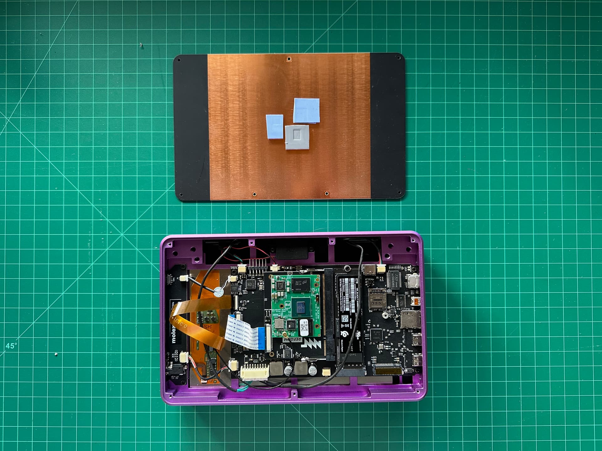
I’m using the IMX8MP module with a heat thermal pad configuration like this:
I used s-tui to run a stress test, with an ambient temperature of about 30C and a ceiling fan (it’s warm where I am).
Using the original PCB back plate:
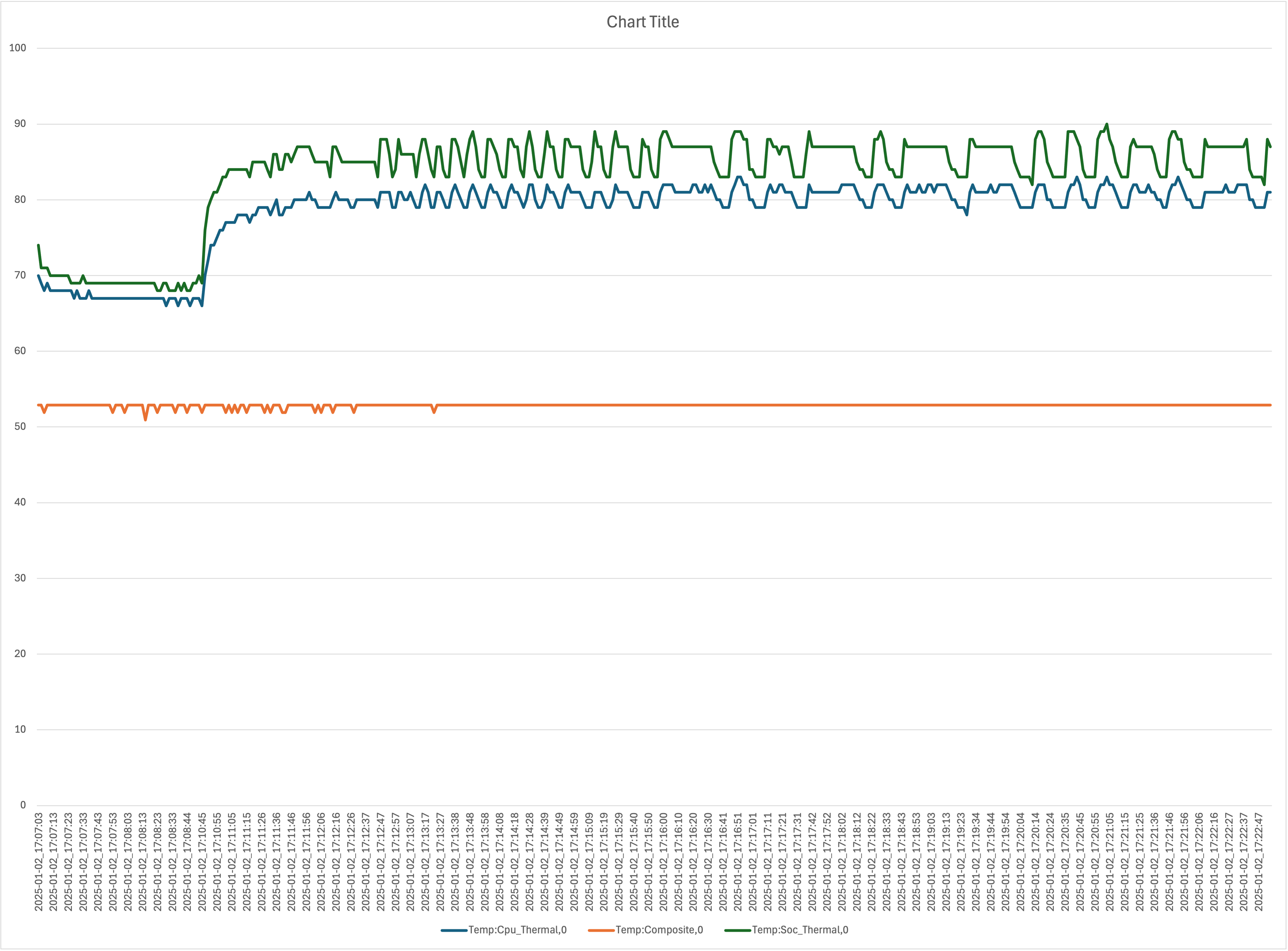
The CPU reaches around 85C and sits there under load.
With the replacement aluminum back plate:
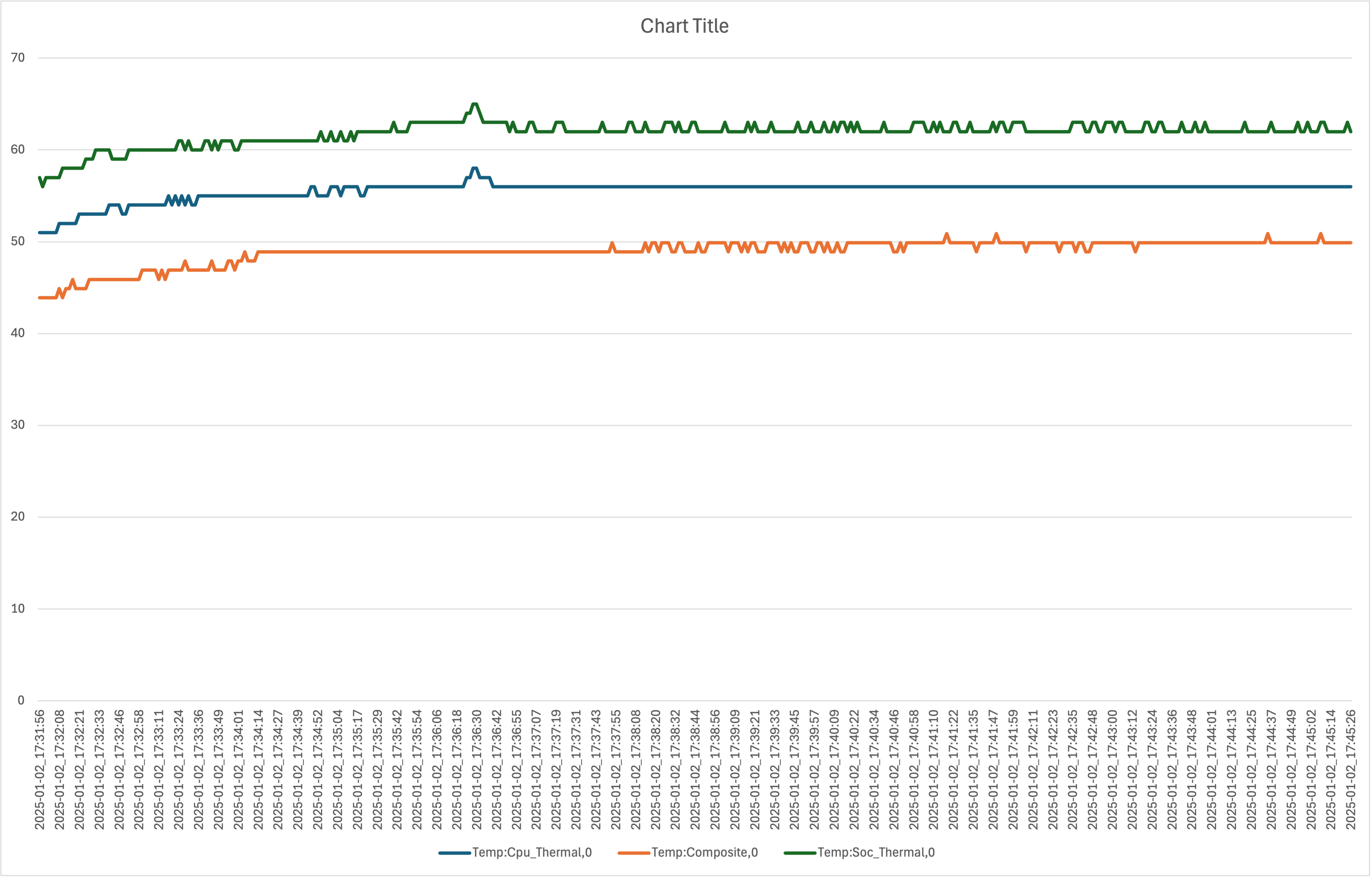
The CPU sits at 56C under load; a roughly 30C reduction over the PCB back.
I’ve not included the CPU frequency in these charts, but with the PCB back it throttles almost immediately, and I’m not seeing any throttling with the aluminum plate.
I opted for the purple anodized finished from PCBWay which matches the purple finish of the Pocket Reform well.
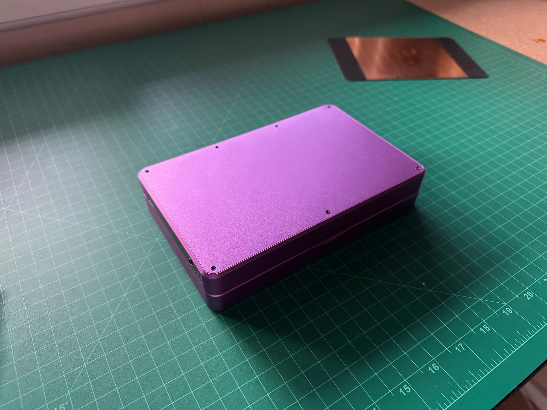
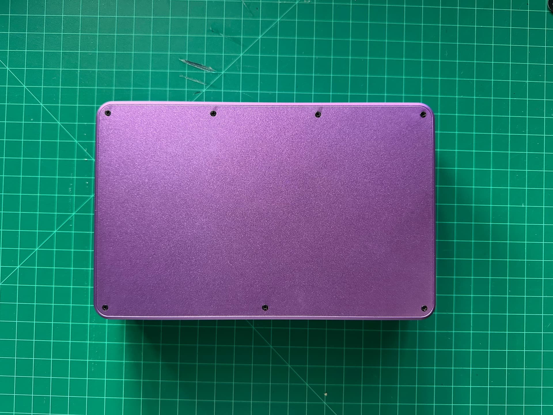
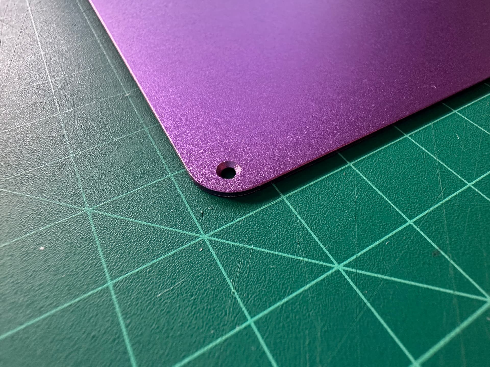
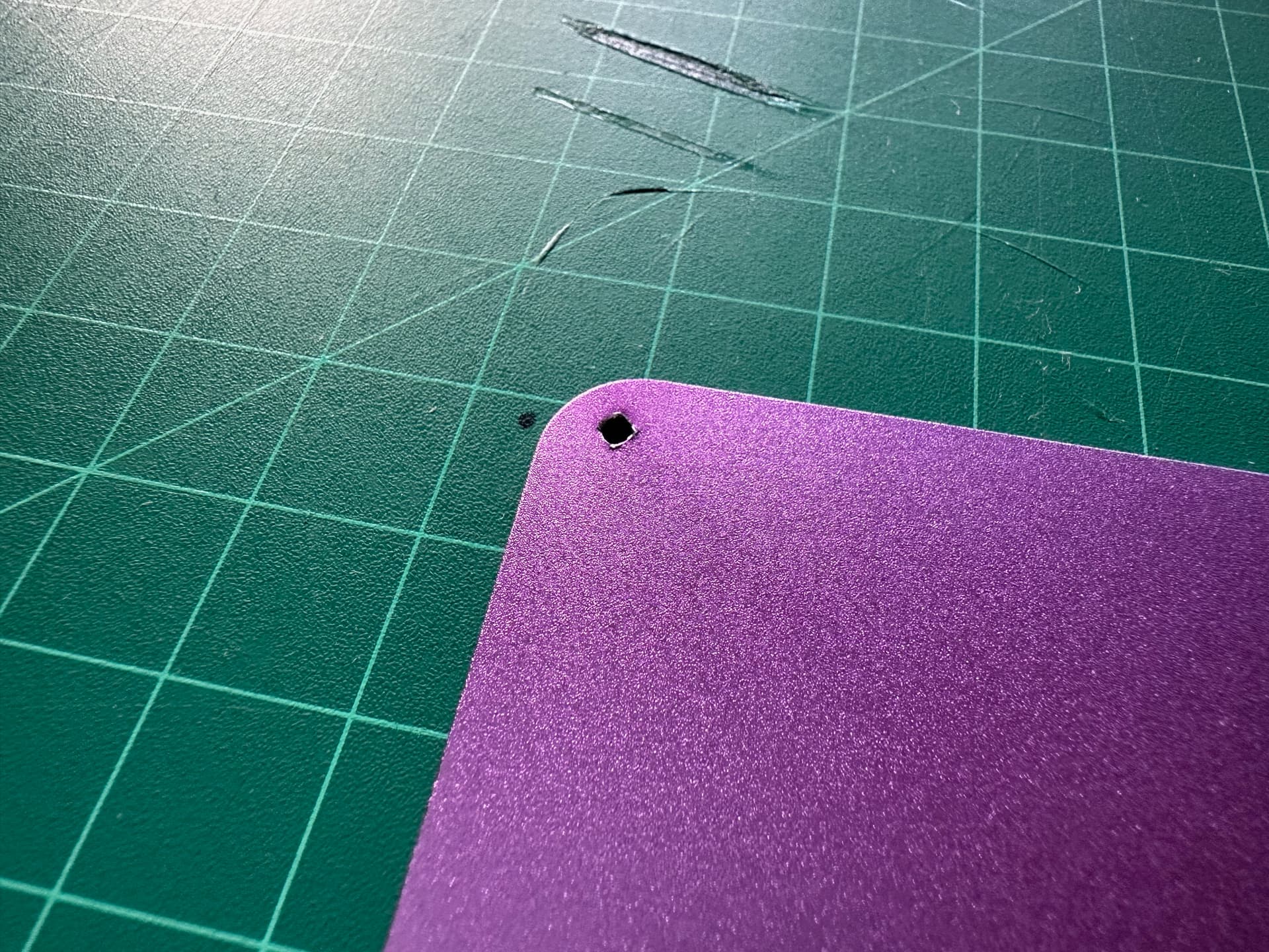
There’s a slight imperfection to the finish on the back near one of the holes where they’ve clearly mounted it for the anodizing:
The STEP and technical drawings are on my GitHub at GitHub - jbmorley/pocket-reform-backplate: Replacement aluminum CNC backplate for the MNT Pocket Reform.
I’m more than happy to help folks work through the process of ordering one.
20 Likes
That’s a beautiful finish and nice that people can reproduce my findings (since I had only one pocket to test)!
3 Likes
…posts a couple of graphs anyways. ![]() Well done!
Well done!
3 Likes
Looks very nice!
So, I had a look at pcbway, selected “CNC machining quotes” (because that looks appropriate), uploaded the step file but now I’m stuck at a lot of questions I don’t know how to answer. Are the defaults fine? Did you only adjust the surface finish but use the default “Aluminum 6061”? What about tolerance and surface roughness?
Yes, it can be a little overwhelming can’t it.
Here’s the summary of my order:
| Material | Aluminum 6061 |
|---|---|
| Process | - |
| Threads and Tapped Holes | No |
| Applications | - |
| Inserts | No |
| Parts assembly | No |
| Product description | Office Appliance and Accessories >>Computer Enclosure |
| Part tracking | - |
| Quantity | 1 |
| Color | Silver white |
| Surface finish | Anodized - Bead blast + Anodized color - Purple |
| Tolerance | No tighter tolerances required (ISO 2768-1) |
| Inspection | Standard Inspection (No report) |
| Hardness | - |
| Finished appearance | Standard |
| Other special request | Please countersink the holes to 3.5mm 90 degrees, as per the technical drawing. Thank you. |
You’ll want to upload both the STEP and the PDF.
6 Likes
And yes, you want CNC.
2 Likes
If there’s a lot of interest in ordering this part, I’ll take a look at setting up a shared project on PCBWay to make it easier. I’ll take a heart on this post as an expression of interest :).
22 Likes
Just ordered using @jbmorley’s files and instructions from jlcpcb, will report back
6 Likes
Exciting stuff! Looking forward to hearing how you get on.
Thanks! My order is through review and heading to fabrication.
2 Likes
Well that was a bit of a let down—I’ve uploaded everything to PCBWay’s Shared Projects, but can’t seem to find a way to set any of the manufacturing defaults for shared projects so if you click the order now it’ll default to a 3D printed plastic backplate. Given that, I’m tempted to just encourage folks to order their own directly as @deianara and @rwv have done, or perhaps if there’s a lot of interest we could do a bulk order to save a little on shipping from China. (I’m in Hawaii though, which doesn’t make it super cost-effective for me to ship stuff out.)
Do any of you folks have experience of PCBWay Shared Projects. Am I missing something?
3 Likes
If anyone is interested in something like this, I have a friend-of-a-friend who has a machine shop in California. I’m talking to them about getting custom Reform parts made as part of a group buy and will start a separate thread about that soon.
9 Likes
How do you measure the temp data? I can tell that mine is hot and if the temperature is messing with wifi that would be explain a lot of things.
You can use the sensors command from the command line. It’s in the lm-sensors package:
sudo apt install lm-sensors
It’ll give you output something like this:
nvme-pci-0100
Adapter: PCI adapter
Composite:    +42.9°C  (low  =  -5.2°C, high = +89.8°C)
                       (crit = +93.8°C)

cpu_thermal-virtual-0
Adapter: Virtual device
temp1:        +40.0°C

BAT0-spi-1-0
Adapter: SPI adapter
in0:           8.38 V
curr1:         0.00 A

soc_thermal-virtual-0
Adapter: Virtual device
temp1:        +43.0°C
For monitoring over time I used s-tui which has a built in tool for running stress tests.
4 Likes
Thank you for the files and thorough testing. I’m going to get one to hopefully resolve the heat issues.
I may make a modified version in the future. I had an idea for a backplate with a slightly raised area covering most of the back, with regularly spaced holes for a grid of neodymium magnets. (And a recessed MNT logo in the center.) This grid could be used to “snap” various accessories onto the lid for temporary use. I am juggling too many commitments so I may not get to it for a while, but if I manage to get it done then I’ll share the files here.
3 Likes
@jbmorley kk so when I’m doing the stress test I’m getting (Temperatures in Celsius):
Cpu_thermal, 59.0
Composit,0 44.9
Soc_Thermal, 60.0
Which I assume is leading to the hotspot. Idk too much about the mechanical side of computers though. So swapping the lid and/or adding a heatsink would fix this?
It may have been answered somewhere before, but with the RK3588/wifi card and a custom top ordered using one of the templates here (PCBWay)
- what thickness/size thermal pads would I need (don’t want to put too much pressure on the PCB, but also want it to make good thermal contact)
- how should the wifi cables be routed to avoid cutting out (I’m using an external one atm, as the wifi does cut out when the processor starts to get warm)
1 Like
I would be interested!