Hi,
First off: this is only relevant if you have a trackball V2. These have clicky buttons and a chip with a raspberry logo on them. We made these during the chip crisis when we couldn’t source the original AtMEGA32u2 anymore.
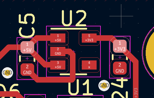
I discovered an unfortunate problem with the RP2040 trackballs today while servicing an MNT Reform. The boards had a design error where 5V instead of 3V3 was going to USB_VBUS of RP2040. We fixed this in production by bridging the south pads of C3 and C22 with a zero ohm resistor. But we forgot to cut the trace supplying C22 with 5V. This results in the 3V3 rail on the trackball board to carry 5V, and in turn also the sensor is powered by 5V instead of 3V3. It appears that this can lead to failure of the sensor over time.
If your sensor on Trackball V2 breaks as a result of this, we will mail you a free replacement in a letter (you can claim this by contacting support@mntre.com).
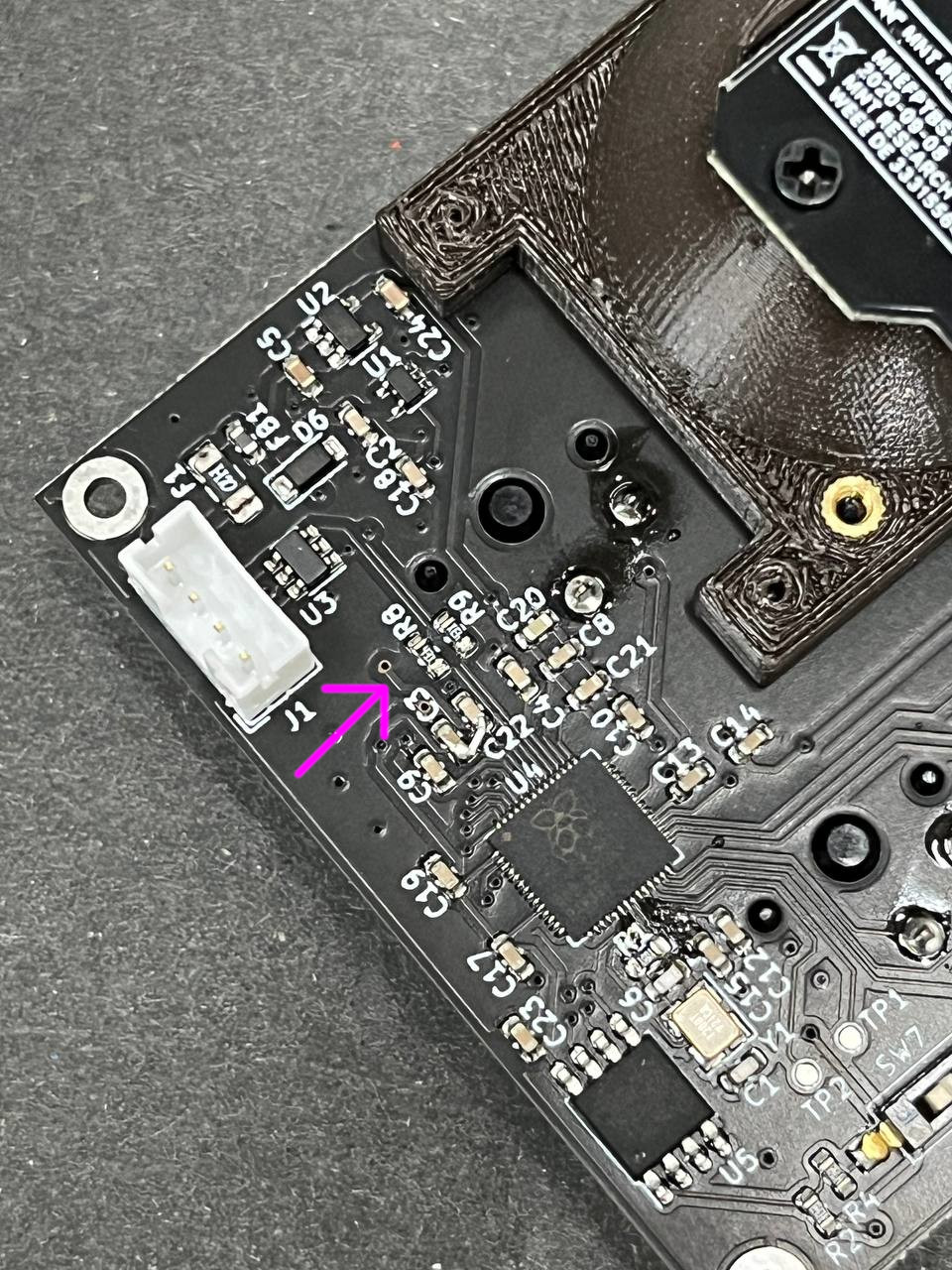
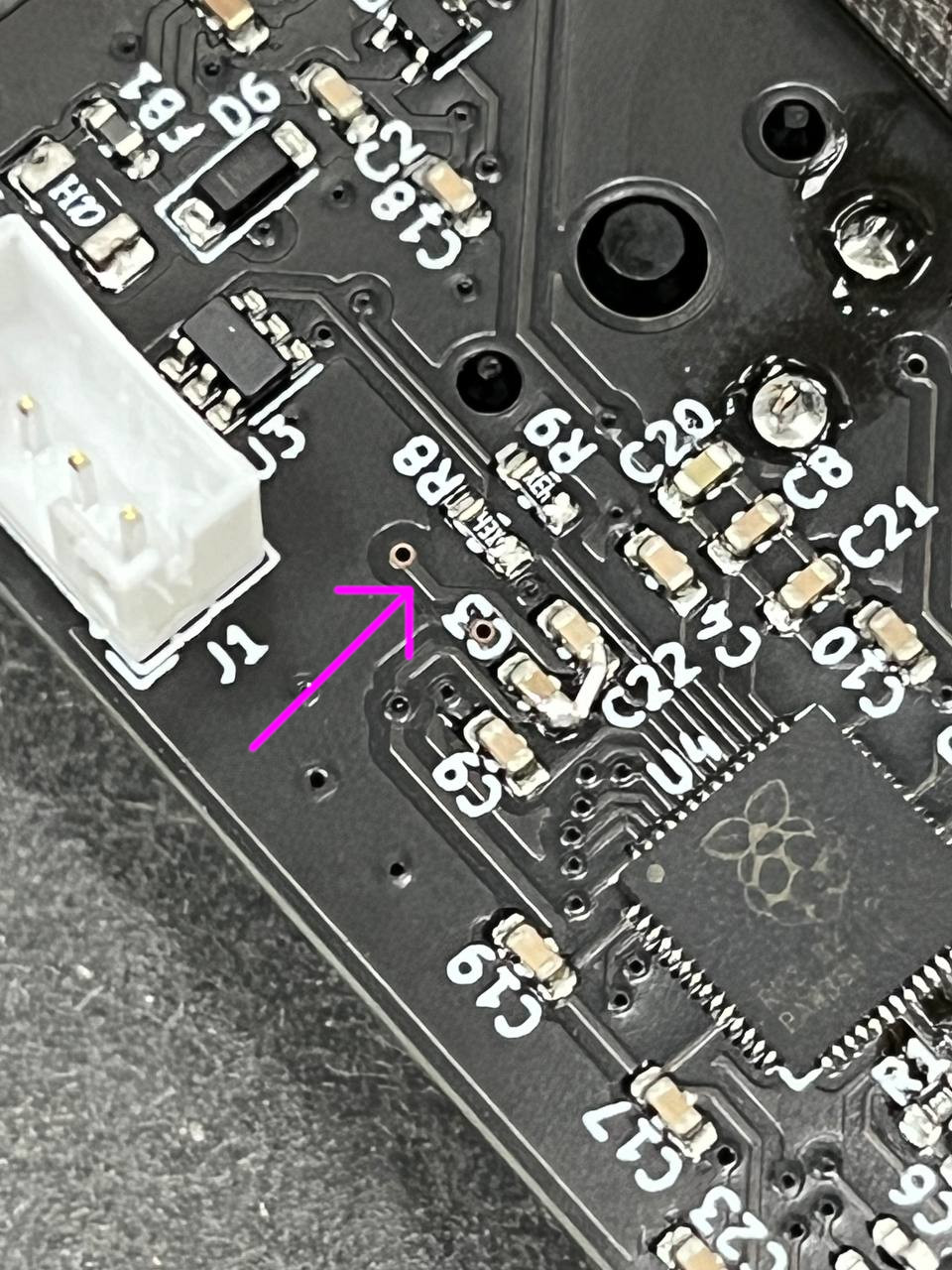
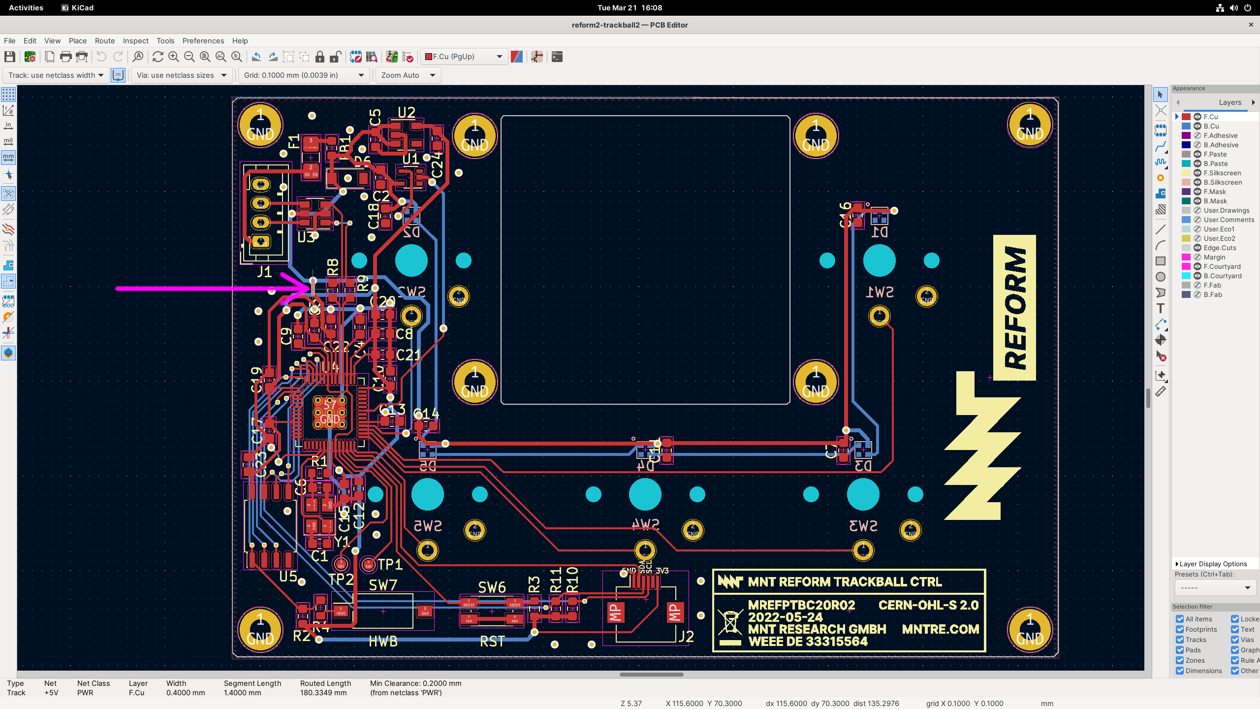
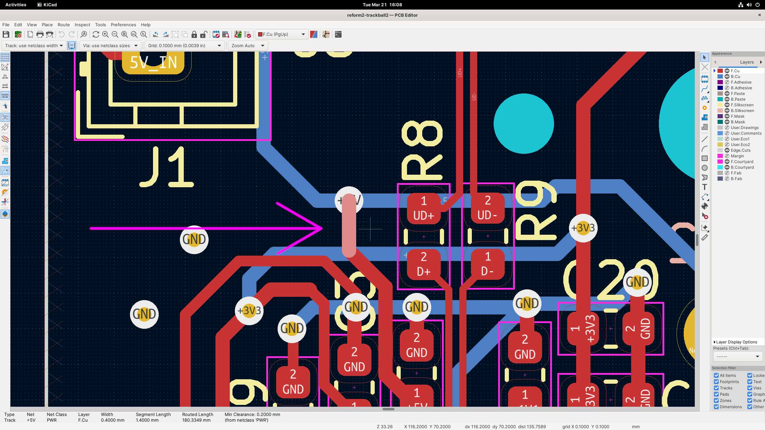
To prevent failure of the sensor, please cut the following trace on the main trackball PCB with a scalpel or sharp boxcutter:

Here are some photos and images to help you locate the trace:
I apologize for this mistake and the inconvenience caused.