I have an iComp Lyra 3 PS/2 KBD adapter.
It does the heavy lifting, but not the reset signal generation, so the PSU’s Arduino is doing that one extra thing for me.
1 Like
I’ve sort of … thrown some sand in the gears overnight…
Decided… since I’m putting a ridiculous sum of money into an A500, that I want a nice keyboard for this build.
In order to fit under the Checkmate 1500 it has to be less than 38cm wide and 3cm tall. I’ve had MacBook Air’s for 12 years now, so I really love backlit keyboards. I prefer Cherry MX stems because of all the third party keycaps, CNC aluminum custom, PBT options, etc… Obviously, I need PS/2, which most modern boards no longer support, now that that they have moved to n-key USB. I really don’t want a bunch of silly logo’s on the board and want a plain black look to match the case. I’m not a fan of loud clacky keys, so MX brown or MX clear would be nice.
All that painting me into a pretty small box of choices.
I’ve ordered a WASD Code 87 Keyboard, will take about 10 days to get here.
In the mean time my cable collection is just about complete for keyboard, mouse, PSU. And I managed to get almost everything in black.
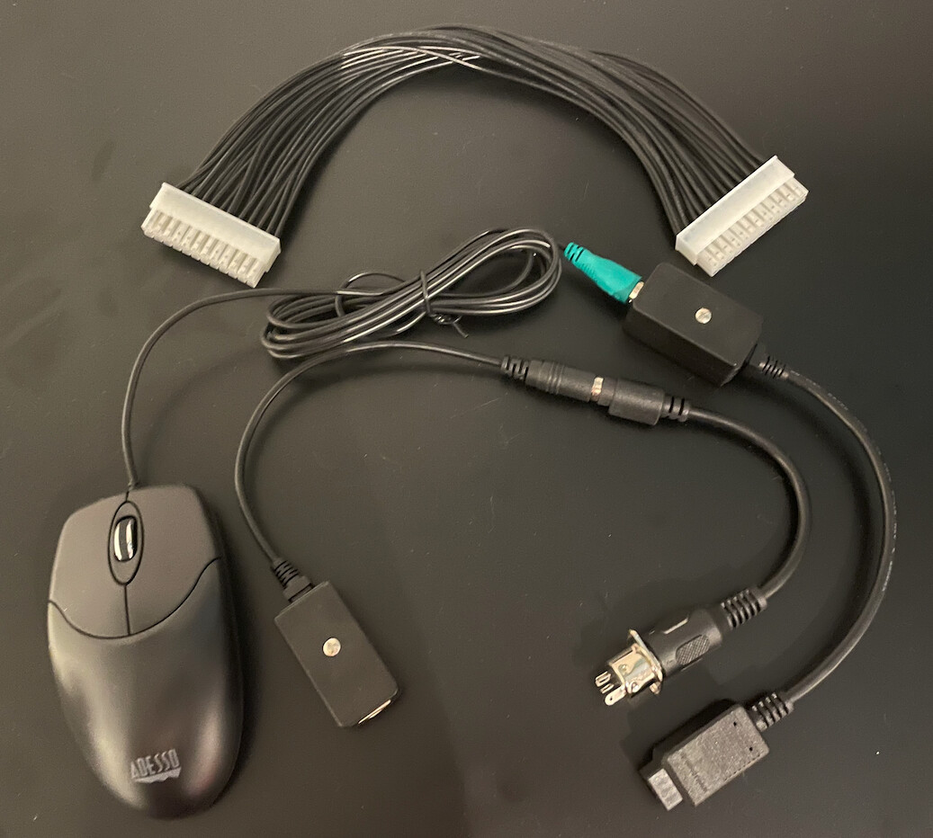
Things just look better when they are ‘real’
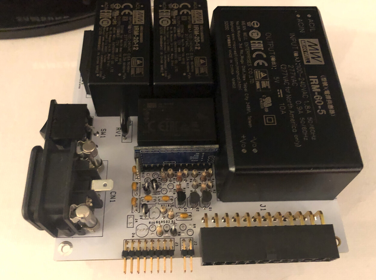
Still needs the fan and diagnostic LED installed…but this is where I am getting the Arduino performing the reset.
1 Like
ATX Power Switch ON-OFF-ON-OFF working perfectly.
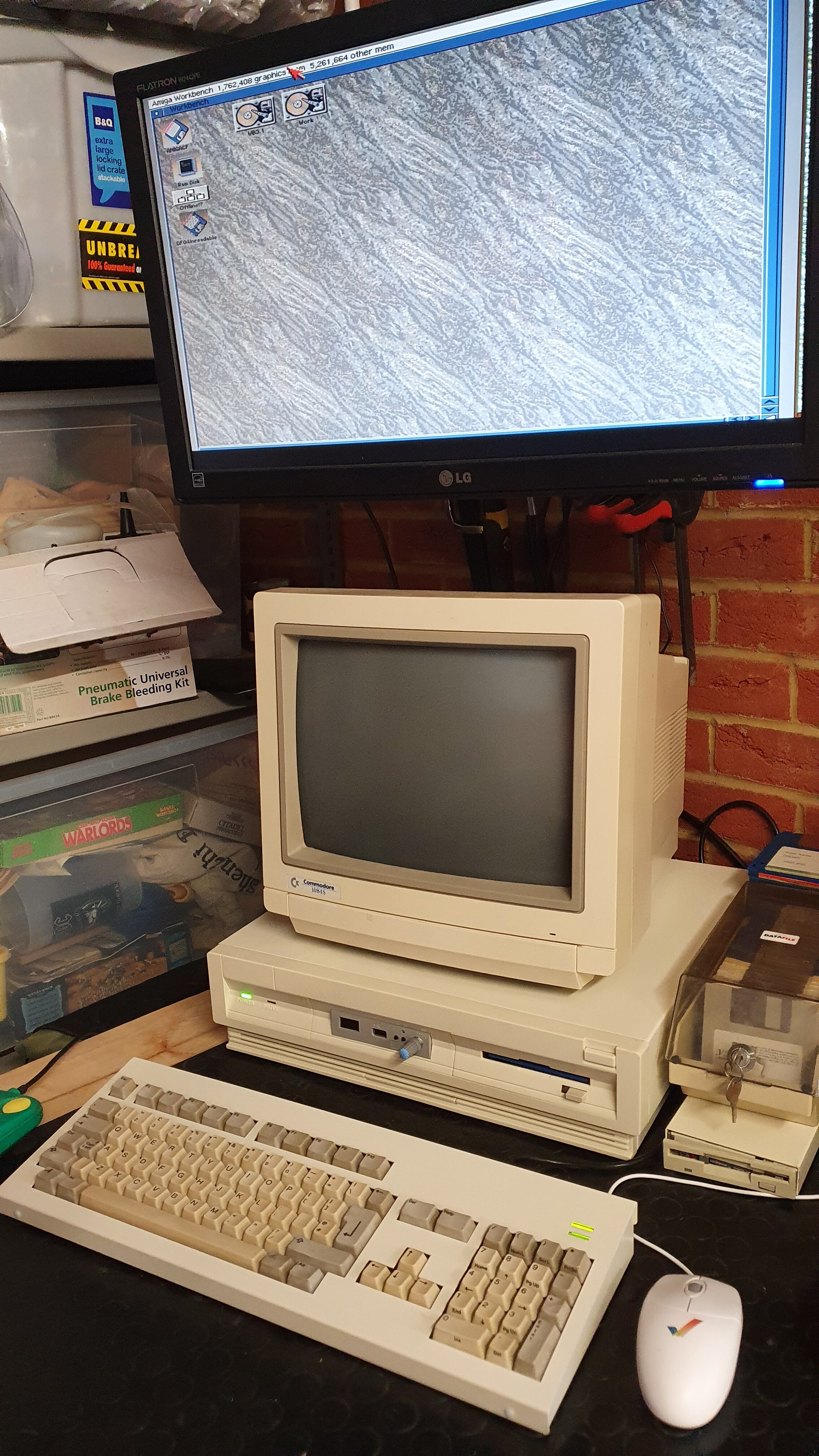
Playing celebration MOD files !!! 
Switched over to KBD reset efforts now.
Go MNT Research shipping team…
I’m ready for you now, got plenty of power 
1 Like
Great work, well done!
Top, top work here. My Checkmate Case arrived and I’ve now got everything installed. I purchased a PSU from Steve Jones @Checkmate and everything works well, except…
I tried to be a little clever and have my internal floppy and GOTEK drives housed inside the case via an A2000 Dual Floppy cable and power Y splitter from the motherboard headers. The drives work without issue, but the GOTEK and the ACA500plus are touching and the GOTEK pushes on the DisMo of the ACA500plus, which pushes it up at an angle that causes the amiga not to boot. The ACA500plus seems really precious about how it is connected via the Zorro adapter and any slight incline causes a boot failure…
To that end I’ve bought some IDC ribbon cable and 2mm connectors and am hoping to relocate the DisMo so that the ACA500plus gets the clearance it needs. At the end of the day it’s upside down and not much use at the moment, so I may as well see what I can do, perhaps a small 3D printed enclosure I can place on top of the case might be good.
@ljmarent, is that orange block under your ACA500plus a 3D printed support of some kind, I think this is definitely needed, especially if putting on an A1234/A1260 accelerator card in the future.
And yes, MNT Shipping team, do your thing. (How do we know which shipping batch we’re in?)
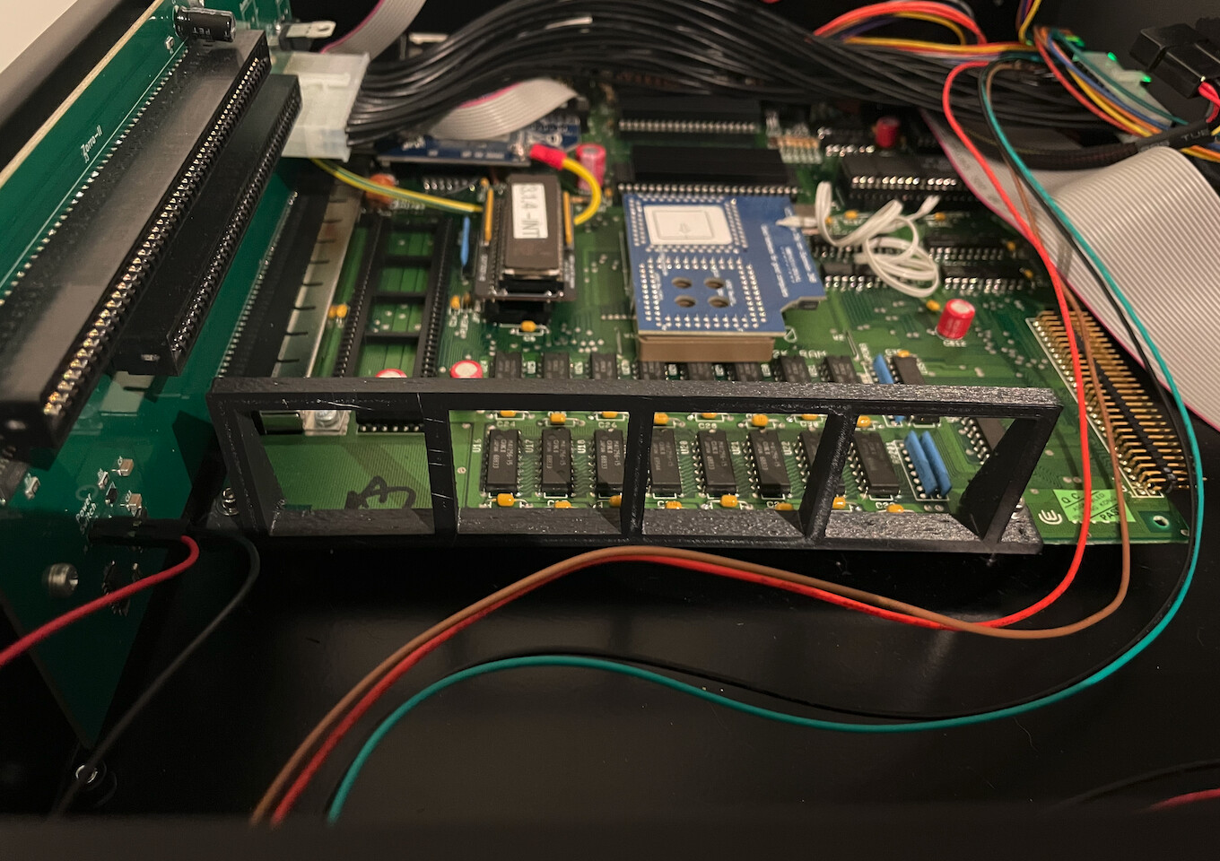
I’ve actually been working on a proper 3D printed support bracket to support the ACA500plus. It sits on the A500 motherboard and uses the front two screw mount points.
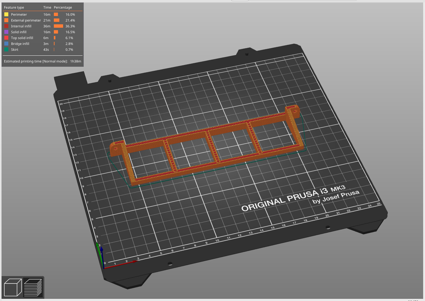
I’ve only just sent the model to the printer for test fit.
I will update the model until it fits correctly.
1 Like
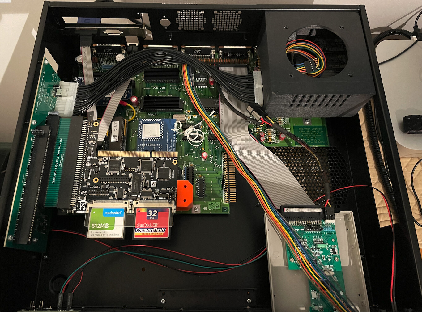
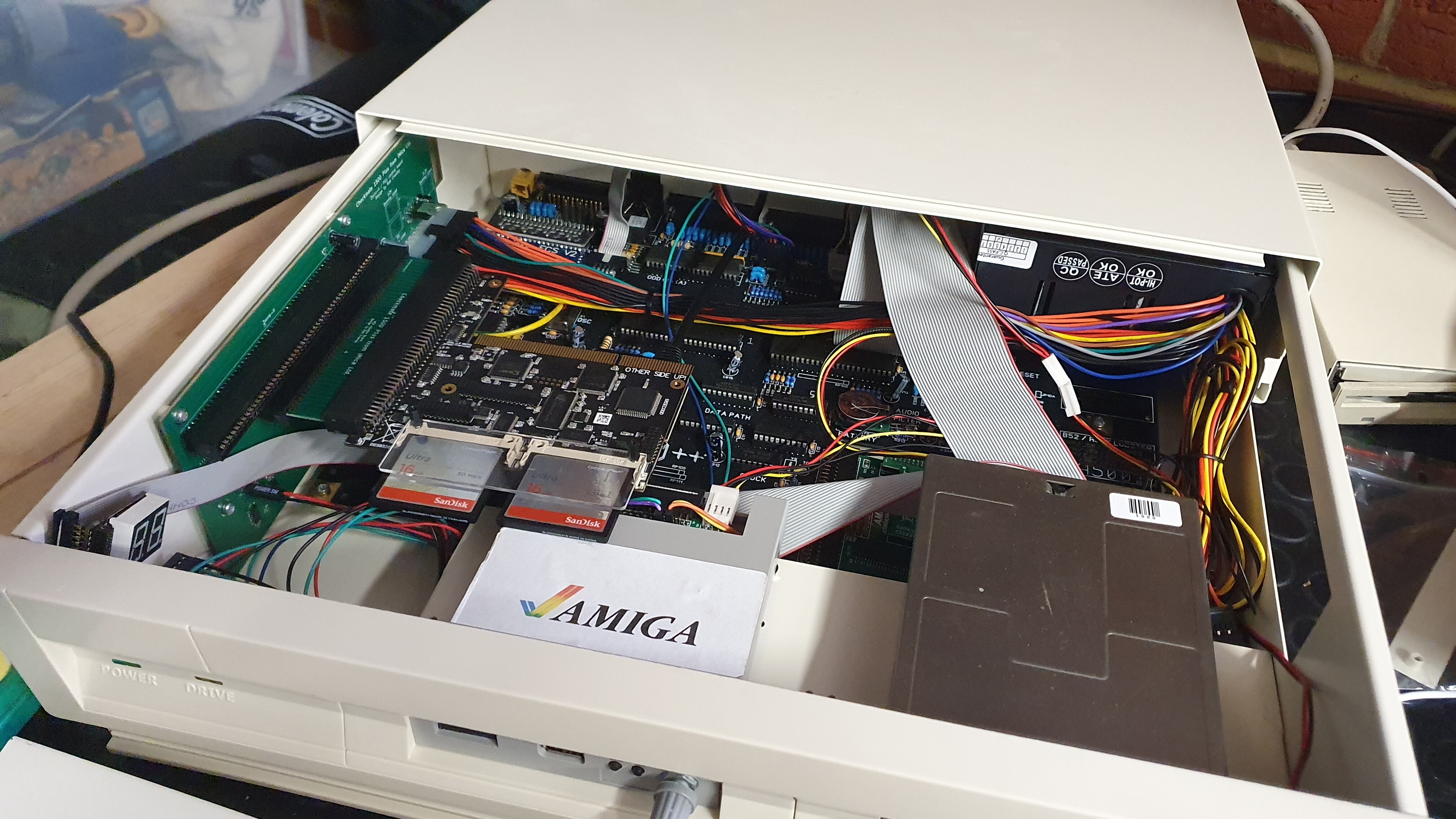
That’s cool very cool, I could probably use a shortened down version To accommodate my Gotek in the second drive slot.
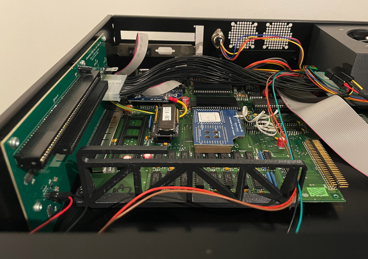
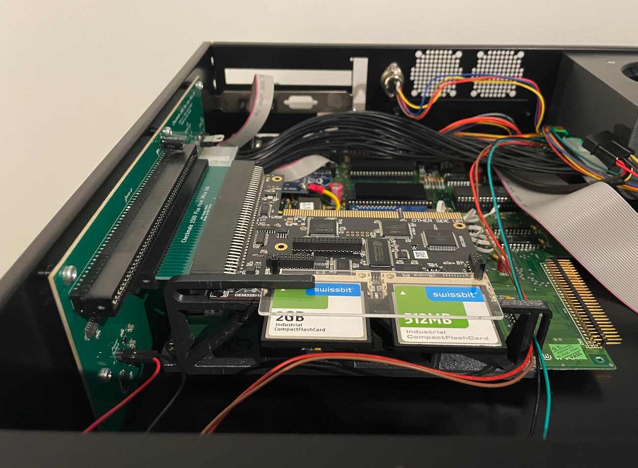
You’ll see here how the Gotek is under the ACA500plus on mine:
Here is the original gap between the floppy drive connector and the reset button on the DisMo, but I’ve just modified the GOTEK and moved it forwards 7mm which appears to have solved my issue with spacing.
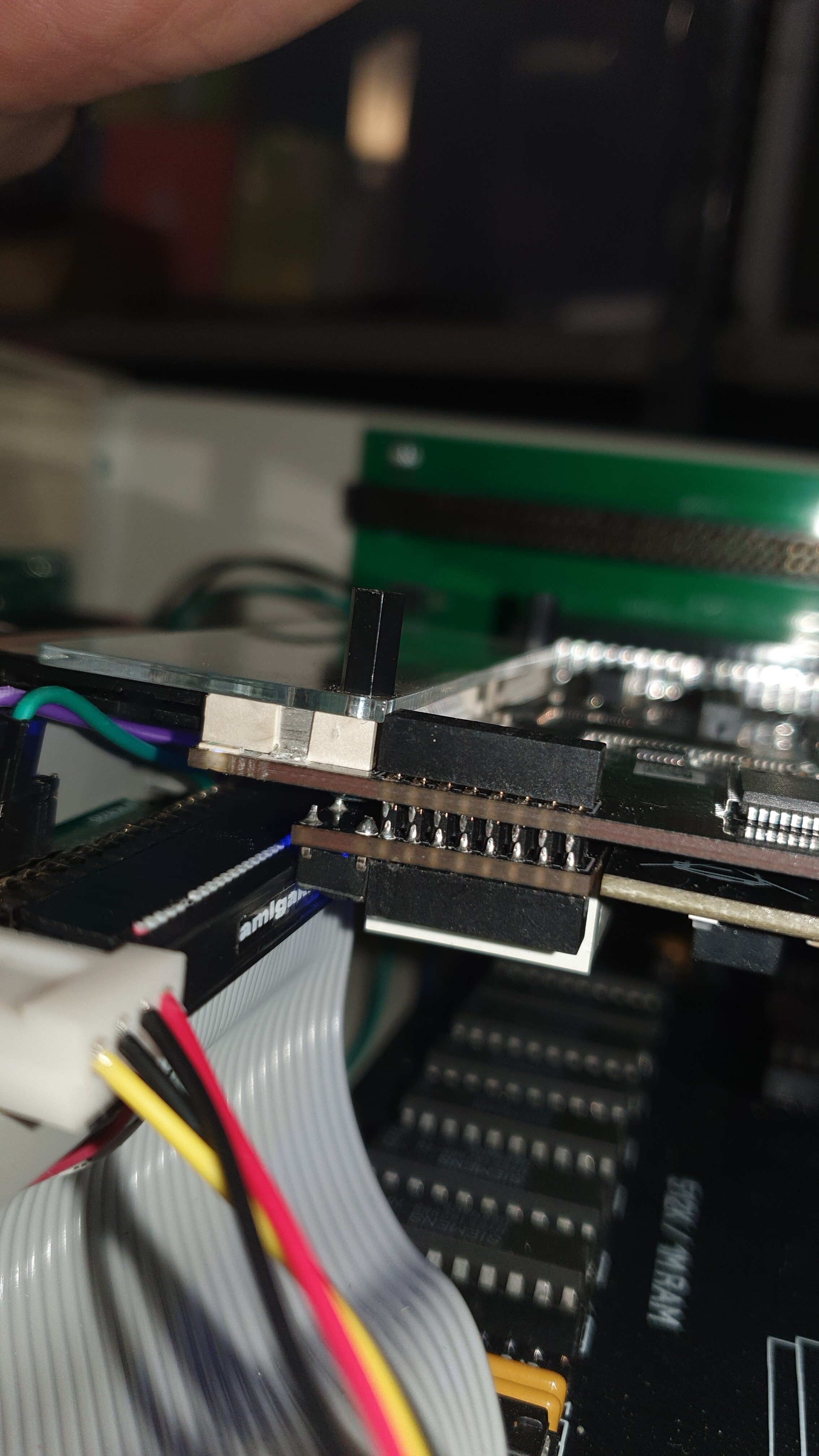
The gap after:
Now all it is awaiting is the ZZ900 to top it all off, I may scrap the idea of relocating the DisMo, but I think it would be a fun project. Another few things I am considering are to out a CF extender to the slot a the bottom front of the case (although with the USB on the ZZ9000, this might be unnecessary) and running some sort of connection from the front ‘Drive’ activity led, to that on the boot card activity LED of the ACA500plus (although that could be beyond me.)
Since the Gotek grey does not really match the cream colour of your case…
Perhaps a new 3D printed Gotek bracket that’s not so in the way…
Like a cousin to this → 32mm floppy drive Gotek + STM32 + OLED bracket by Carcenomy - Thingiverse
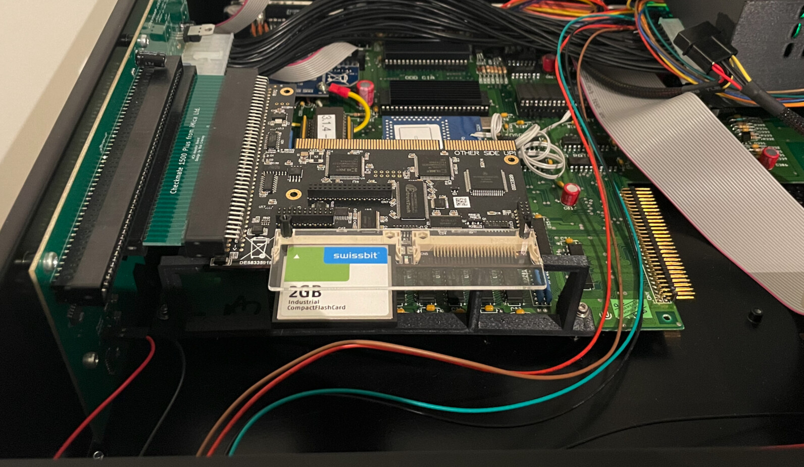
Here are pictures of my finished bracket:
Yes, I could probably shorten it up to work for more people…
I’ll give that a go based on your photos
I was actually thinking of spray painting the Gotek, the same oyster white as the case, I might ask Stephen Jones what the RAL color of the case is. It actually really bugs me that it doesn’t match (as does the green solder mask on the Zorro Expansion boards against my black A500++ and ACA500plus.)
Well…the easy fix for the PCB solder mask colour is to close the case
But yeah, the Gotek is a little harder to pretend
I have a black Gotek on the way…and black is a little easier to ‘match’
I also use a colour programable LED in my PSU, and initially set it to black, but it was hard to see when the PSU was on …
Stephen has just sent me the RAL colour, so I’ll order that and some plastic primer, then make it all look right.
Out of interest what have you done in regards to the drive light on the case?
1 Like
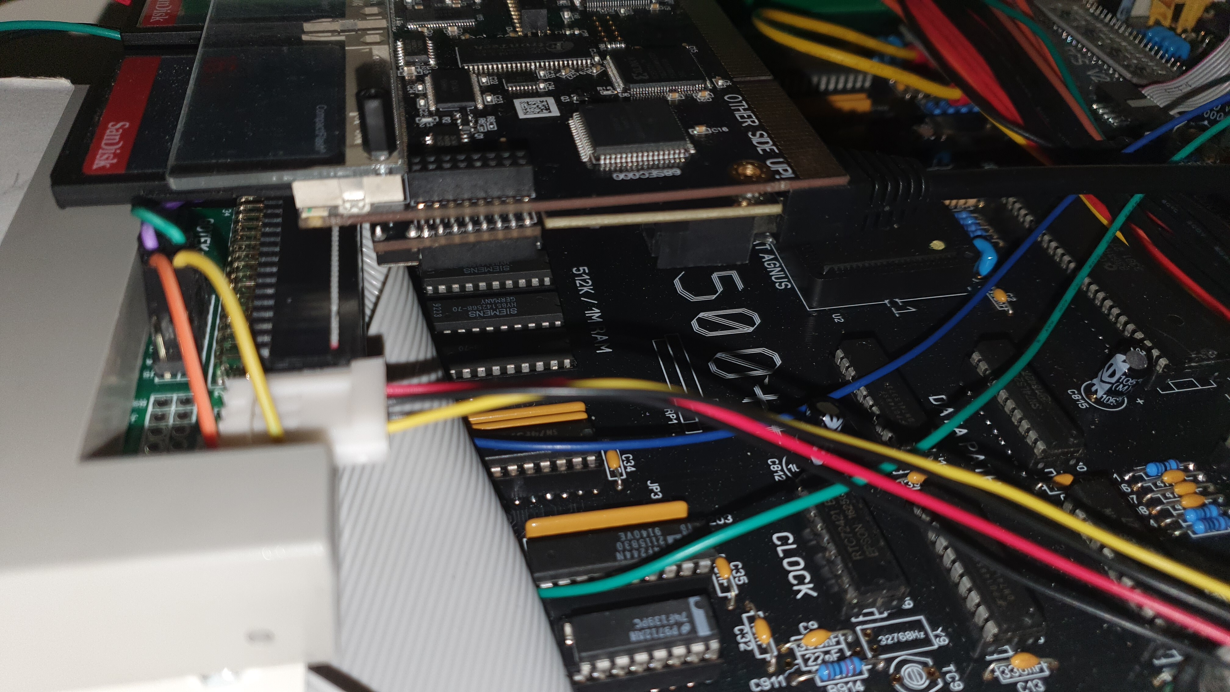
Since my PSU talks to the keyboard connector, I grab the PWR and FLPY LED signals and break them out, so that it’s like they were plugged into the motherboard…I do add the DIMing resistor, since my board is a rev5 A500 which fully turns the PWR LED off when the audio filter is on. I don’t like the power light going out, so I keep it DIM like the rev 6 and later boards do.
I’ve updated the CAD to include a shorter version for people with a Gotek in the second slot
I’m looking at the ACA500plus and wondering…
Once the ACA1233/4 030 card gets here, how best to support it ?
There are no screw mount points on the A500 motherboard below and nearby where the 030 card will be plugged in.
There are three screw mount points on the ACA500plus itself…
Perhaps a printed bracket which mounts to the ACA500plus screw holes, and extends towards the rear of the case, so the 030 accelerator can rest on it, taking the strain off the 1200 connector.
May also need to incorporate a mount point for a fan in that bracket, as we will be mounting the 030 CPU and its heatsink upside down.
I saw the iComp response on the ACA500plus drive activity LED in the forum.
You know…I searched for his prior Q&A and could not find in a reasonable time, so he should be a little more accommodating. Anyway, looks like yucky jumper wires … or … you know we could maybe use photo-diodes to contactlessly sense those white LEDs on the ACA500plus ?
The Drive Activity LED is high side switched, so 2x photo diodes mounted on the printed support bracket could pull a PNP transistor base to ground when either sees the white LED.
Would need a tiny PCB to sit on the A500 KBD connector to pick up
+5V, GND, Drive Activity LED and connect the two photo diode leads.
I’ve asked him to provide a link to the post he mentions. I don’t mind a couple of jumper wires as I should be able to run the cable neatly as it’s on the underside of the card. I may utilise the connector already provided with the case.
It’s whether I can solder finely enough on the existing LED!
I’m not sure exactly what you want to do…but I suspect the ACA500plus will use low-side switching of the LEDs and if you only want those two to drive the LED, that should be fine. If you still want the floppy activity to also drive that LED, that’s high-side switched and you’ll need to put something between the two signals to merge them.