I’m using Indivision ECS modules in my A500’s, and one of my A500’s is getting a ZZ9000 as quick as you can ship
I’ve ordered the Denise interposer board for my ZZ9000, however ‘it seems’ like MNT has not really anticipated or planned for co-operation with Indivision ECS modules.
I’m considering a couple options:
I can remove the vertical IDC connector from the MNT interposer board, replace it with a right angle IDC connector, then add a 48pin IC socket to increase vertical clearance, before seating the Indivision ECS.
I can remove the vertical pins from the Indivision board and replace them with pass-through socket pins, so the MNT interposer can be placed on top of the Indivision ECS.
Jens has also just suggested I solder a 48 pin socket on top his Indivision ECS board, which is really the same as the option above really…maybe a bit lazier
Are there any other options I should consider ?
Has anyone else already done this, solved this issue, maybe I’m completely wrong, just going by photos ?
Any chance of an interposer with the IDC header on the Vidot side of Denise ?
Thank you,
Amiga model: A500 rev 5
680x0 CPU: 68030
RAM Configuration: 2MB Chip, 128MB Fast
Kickstart, AmigaOS Versions: KS3.2, WB3.2
ZZ9000 Firmware version: Whatever you ship it with
ZZ9000 Driver version: Whatever’s in the box or on the support site that day
The Indivision ECS V2 ‘is’ my Super Denise.
Replacement chips have gotten crazy expensive, and given their age and dwindling numbers, won’t last. So I made the leap to the Indivision ECS.
I’m in a similar boat to you, but I managed to find my Super Denise chip in my box of spares. Having purchased the ECS V2, I’d like to utilise it if possible. Preferably with as little hacking as possible.
I’ve been reading your posts on the iComp forums and it sounds like we will have very similar setups (A500, ACA500plus, A1200 Accelerator, Checkmate 1500 plus case and ZZ9900). Perhaps some collaboration when it comes to setting it all up is in order?
Sounds good to me.
Jens has supplied some ‘useful’ information on the ‘back channel’ but publicly, as you can see, will not be supporting this ‘craziness’
I wish he’d open up an ‘unsupported’ channel for all the hot-rod builders who clearly like and buy his stuff.
my ‘solution’ is to rotate the ribbon cable connector on the MNT Research Denise interposer with a right angle connector, for now, because that board is a lot less complicated and less expensive if ‘anything’ goes wrong in reworking. Maybe I find the schematic for that little board some day and just lay it out a little different, so the ribbon connector is at the back instead of the front. And make the Gerbers available to Indivision ECS users. But I don’t want to hold up the fun, so I ‘mod’ for now.
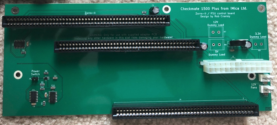
The Checkmate 1500 Zorro II board is ‘neat’ but also a bit of a ‘hack’
Looking at the Amiga 2000, the 500’s bigger sister, the Zorro II slots are buffered by 74xxx series chips and the Buster chip controls the data bus buffer direction.
The Checkmate board is not buffering the Zorro slot and so Jens is concerned that the ACA500plus has to drive the added ZZ9000 AND the added capacitance of the Checkmate Zorro II board. There are some things we can do to improve the ground, increase drive strength and reduce capacitance.
The good news is that the 68030 chip has much stronger I\O drive ability.
And we can tie all of our boards together with nice thick ground straps, crimps, washers and screws, to help with signal integrity. We can also remove the 68000 from the A500 board to reduce capacitive load of the system buss.
There is a way to mod the ACA500plus as well…but I’d like to avoid that if we can do a good enough job with these other techniques.
Having said all this…it’s still not a Jens ‘supported’ use case…
So…if it doesn’t work, he really doesn’t want to know, and if it does work, he doesn’t want to discuss it in such a way that people think it’s recommended or advised.
I can see his point…though I feel he’s better served to provide a little guidance to a few who can help the others, with a giant caveat…that this might not work for you… It makes our hobby bigger when we don’t ‘exclude’ co-operation between toy vendors
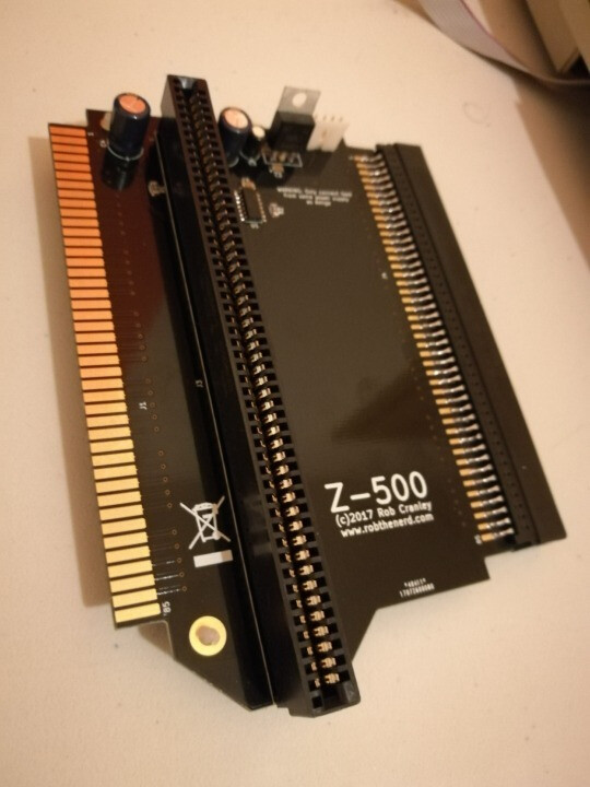
Is the Checkmate Zorro Expansion card not a rework of the Z-500? They’re both designed by Rob Cranley. When asking about compatability with an ACA500plus I believe this is what the team at MNT use.
It is…
But that doesn’t change Jens position that ACA500plus is not permitted to be plugged into anything except the A500 motherboard directly. So we get zero support from iComp in this use case.
Also… The Checkmate 1500 Zorro II board early ones are known to NOT work. So consider the schematic was likely identical to the board above, but the layout broke it. That’s the level of margin we are working with.
The new version of the Checkmate 1500 Zorro II boards does work with my ACA500plus, but I don’t know how well with the ZZ9000…waiting on shipment.
Adding ribbon cables from the ZZ9000 to the Denise or Indivision ECS is creating all manner of ground loops. So until we try it…we won’t know how stable we can make all this.
I will be running heavy ‘star’ grounds where all the circuit cards have a ground wire that ties back to a single point…
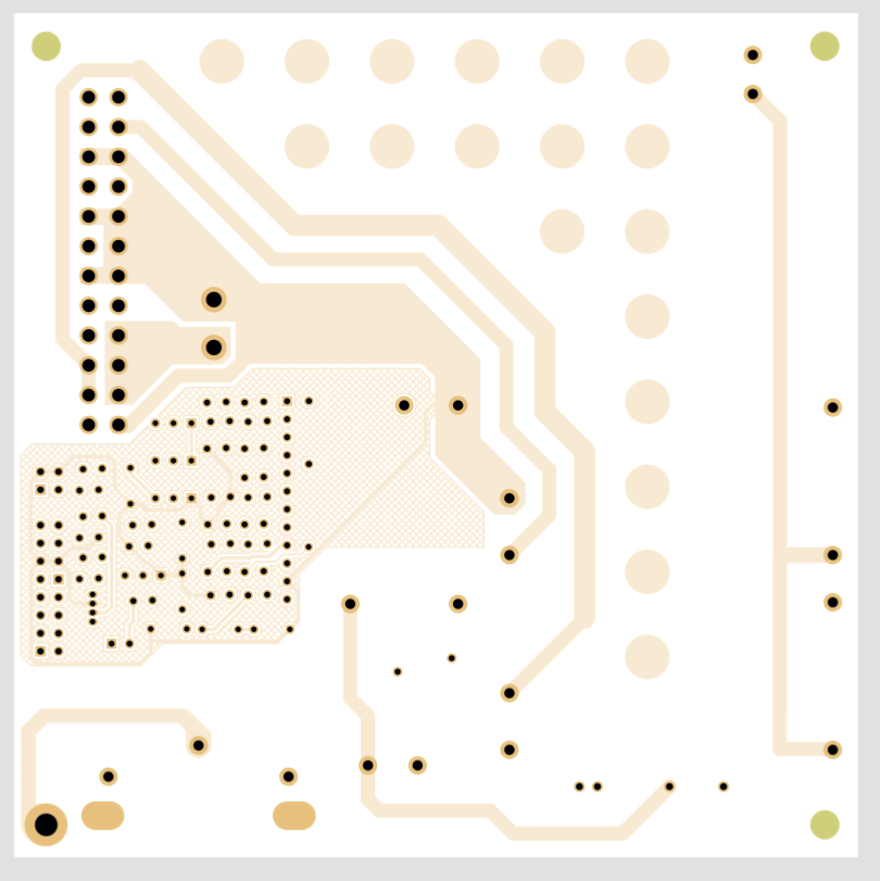
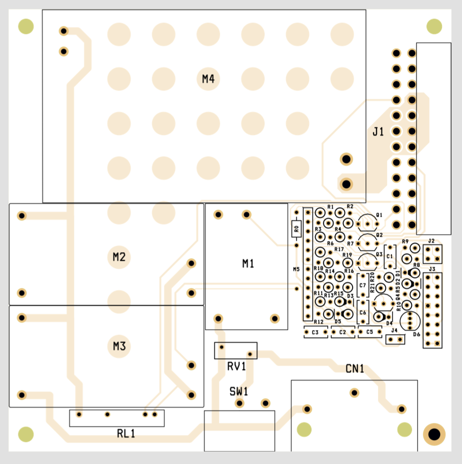
Notice the ATX power supply control traces cut right through the ground pour ?
Notice the signal traces from the CPU port to the Zorro 2 port passed through the ground plane on the old board and came up to the top side ?
Now look how the new board has changed those layouts.
I didn’t find a public explanation, just using my eyes here.
But if this is what caused the trouble…we’re playing with not much margin
Interesting posts! FWIW, I’m personally testing the ZZ9000 in A500 with Z-500, ACA500Plus and Blizzard 1230-IV. This combination works fine for me.
I also have a Checkmate 1500 case with the Zorro adapter, but I don’t have a fitting keyboard adapter, so I kinda got stuck when testing and didn’t get around back to it.
Well…I’m making a little reset circuit…so you ‘could’ use an iComp Lyra 3 PS\2 external keyboard adapter. The reset circuit just waits until the KB_CLK signal has been…um going off the top of my head…low for 500ms, then asserts the A500 reset signal on the KBD connector to reset the machine. So now the A500 takes half a second longer to reset, like all the big box machines. Likely just use a Pro micro Arduino for proof of concept… and bake the circuit into my PSU.
I would not use the Denice Adapter at all…on my A500+ the picture quality was soooo poor…so i used a duel monitor setup with my indi v2 and zz9000…untill i got a PiStorm…then the zz9000 and indi v2 went back in there boxes…six months ago…as the zz firmware is stuck at 1.8 for Ages.
Mark, the quality of the Denise adapter output is normally digital and perfect. I know that it didn’t work out for your setup, but we were not able to figure out why. You could still send back the adapter for a refund. Hundreds of people are happy with firmware 1.8, so I don’t know what your comment about “stuck” is supposed to mean. FWIW 1.9 is around the corner, which fixes compatibility with some monitors, projectors and capture devices.
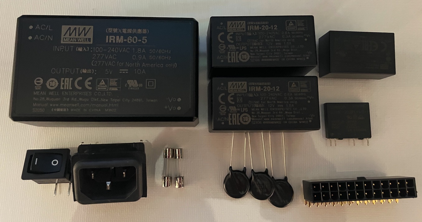
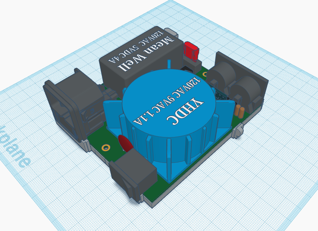
My Checkmate 1500 - A500 SFX form factor PSU design is complete.
Power (independently regulated):
+5V @ 10A
+12V @ 1.8A
-12V @ 1.8A
+5V Standby @ 200mA
Keyboard:
Big-Box Amiga Keyboard input connector
A500 Keyboard with reset output connector
Power LED and Floppy LED output connectors
ATX:
119mm x 119mm, fits in SFX 125mm x 125mm
PS-ON & PWR-OK signalling supported
DC out connector on PSU side, to minimize internal power cable length.
Protection:
2A fusing on AC Line and Neutral
MOV
Over\Under voltage monitoring & Over-Temp monitoring with supply shutdown on fault.
Temperature controlled fan
RGB status LED for fault indication
4mm creepage for high voltage traces
I suspect the Checkmate 1500 Zorro II \ ATX board does not keep the Amiga A500 in RESET until the PWR-OK signal from the PSU indicates that the supply voltage has stabilized. I’ve asked for additional information about this behaviour from Steve. If it turns out that my hunch is correct; then since I have access to the A500 RESET signal, I will hold it low, until after the supply rails have stabilized and PWR-OK is driven high.
This is not a ‘product’ for sale
Once I’ve tested it, anyone who wants the design files will be welcome to them. My hope is that strong, clean power and good grounding will help to make an ACAxxxx and ZZ9000 equipped Amiga A500 reliable.
Steve sent my request to Rob Cranley and I received a confirmation email this morning. The Zorro II \ ATX power board does NOT make use of the ATX PWR-OK signal. So, I will configure the Arduino to assert the A500’s RESET signal until the supplies have stabilized.
The power supply design looks amazing, BTW. I would love to have something like this for my A3000 as well. At the moment, I am using PicoPSU which is slightly underpowered on the 5V rail.
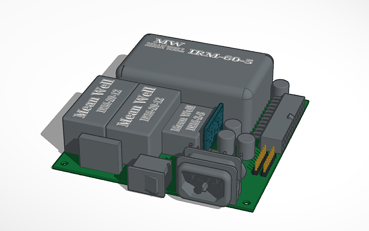
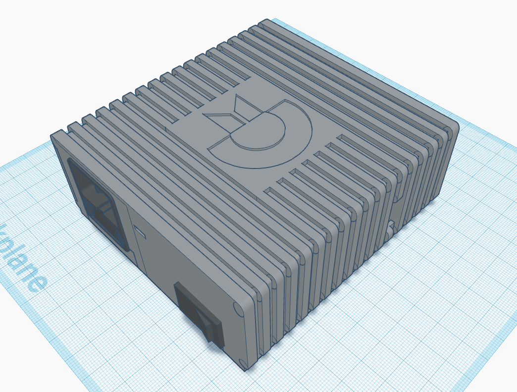
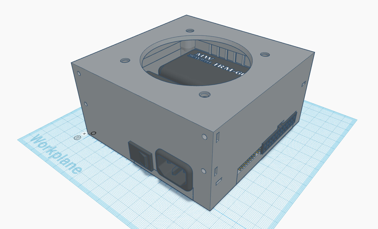
I’m slowly picking away at the 3D printed SFX housing for the supply here:
I’ll ask a local friend for an A3000 PSU to borrow, so I can get the PCB dimensions and model it up in TinkerCad.
The IRM and MPM series encapsulated power modules I’m using run out of steam at 90W, so +5V @15A is about as far as they can go.
Once I have a model, I can see how ‘easy’ it is to spin a PCB and make a printed housing. (I suggest using UL94 V-0 rated ABS for PSU housings)
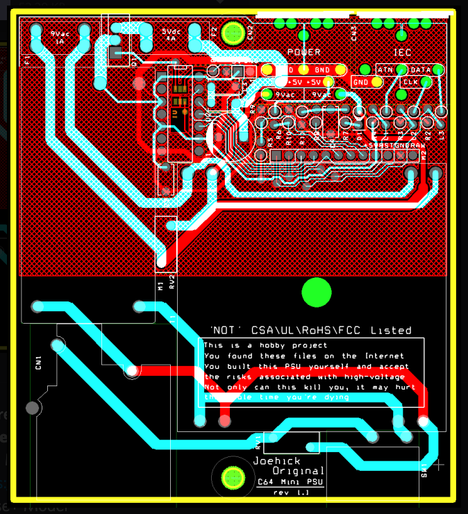
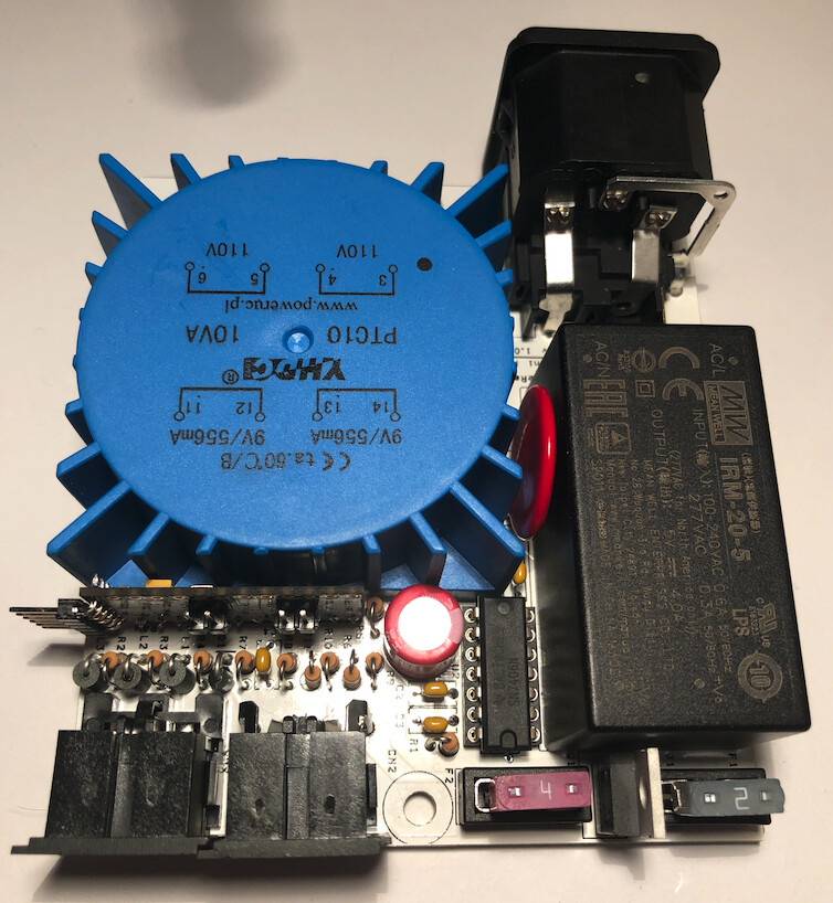
My C64 mini PSU followed the same design path, looks like this:
YAY!
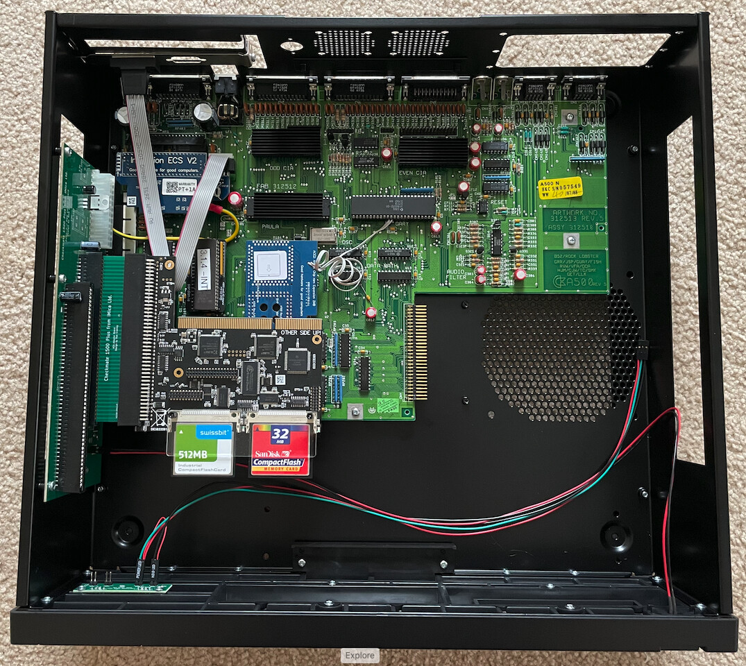
My case finally arrived…no longer a pile of PCB’s sitting in the A500 shield on my desk.
Black Cherry MX PS2 Keyboard and Black PS2 Mouse should arrive via Amazon this afternoon.
Keyboard DIN jack and DIN to miniDIN cable sitting in my mailbox from China.
Power Supply PCB’s about a week away, according to tracking.
Fingers crossed that the iComp team gets the ACA1234 shipping soon
Ohh…I really should heatsink that Gary chip…
Mostly just for looks