I’ve been eyeing a purchase of an MNT Reform (or the upcoming Next, whichever) for a while now, but there’s just been one thing bugging me: the lack of a separate audio input port. Those aren’t usual on laptops anymore, which drives me nuts because they’re fine for things like headphones with integrated mics… but I’m a musician, my input equipment has no listening capability! And an external soundcard dongle not only would just literally permanently live stupidly dangling off my laptop’s USB port, but introduce more latency.
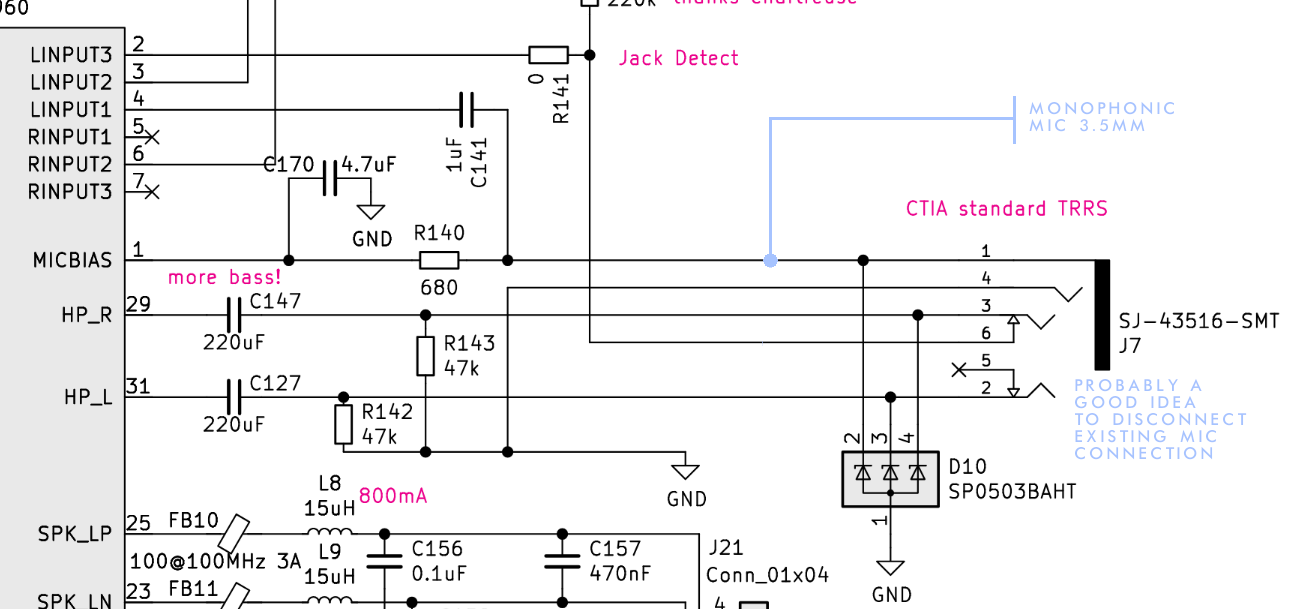
Luckily, I know a LITTLE bit about electrical engineering from trade school, so I took a look at the schematics for both the MNT and for the TRRS jack and it… actually looks like it could be a fairly easy mod to put in a 3.5mm monophonic mic jack, in theory? Not audiophile-suitable, certainly, not XLS or stereophonic, but good enough for me. This isn’t a detailed proposal, just a rudimentary concept, but it looks like you could just connect to the existing line-input connections of the TRRS combined-headphone-and-mic port, something like so:
This is to be clear a simplification, I’ve yet to consider the practical details (see that Jack Detect and the grounding? Have not even thought about them yet.)
I’m basically posting this concept here for a sanity check on the general feasibility, asking if this is even a workable concept or if I’d just be wasting my time down this rabbit hole. And there’s a couple basic questions:
These lines on the diagram I’m junctioning to: what physically are they in real life? If it’s wires or even in a flat cable assembly, it’s a simple soldering job (which would still take a whole frustrating day to make a too-flimsy connection given my track record but is something I’ve done before) or even hopefully doable with something like a wirenut or more likely a wago. But if these lines are etched onto a circuit board, that’s… a lot trickier to DIY. Theoretically possible in that I THINK I’ve heard of people etching new lines onto a circuit board by hand? Or even drilling through to make connections? Even so, it’s something I’ve never even come close to doing before. And doing something with KiCAD and getting a whole other board printed out (apparently only orders in bulk) seems way above my level. Either way, maybe a fun learning experience but not something smart to do for the first time on a machine you actually wanna daily-drive.
It kinda looks like this concept might be easier on the MNT Reform Next than the original, on account of those removable ports on either side? Would it be worth waiting for that, or at least its schematics?
Do we think the software and firmware would take this hardware adjustment in stride? I think there’s some chance of that, that the computer will just think you have a headphone-mic plugged in and that’s that… but then, that could make it think you have HEADPHONES plugged in all the time too, and therefore disable the speakers, or somehow else confuse it when you have a mic input but no output plugged in when it expects those to be in series and now they’re in parallel… A lot could go squirrelly, but I don’t even know what I don’t know.
Does any output or power travel down that mic line?
In my classic Reform I installed a second TRRS jack on the right hand side:
In my own mod, it’s just mirroring the TRRS jack on the left, creating a built-in headphones splitter so that two people at the same time can plug thear headphones in. But this mod shows that there is enough room to install another 3.5 mm jack. Instead of connecting the wires to HP_R, HP_L and GND like I did, you could solder the wires to whatever pin on the motherboard that you like.
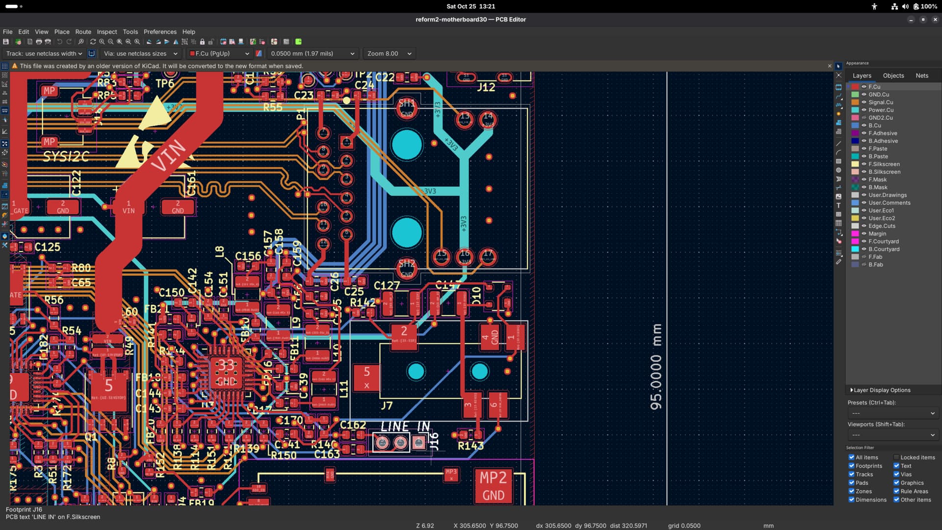
And regarding how stuff is wired, I would recommend to install KiCad (it’s free) and download this repository and open the .kicad_pro file here to explore the PCB design (you can also press Alt-3 in the PCB viewer to look at everything in 3D):
Maybe someone should set up a web based PCB viewer, BTW.
On the Reform Next, a very similar audio jack (but without Line In) is together with SD card, Ethernet (Ix) and USB-C PD on a small “Port Board”. This board also contains the audio DAC/ADC and connects to the motherboard with a bunch of FPC cables. This means that one could completely customize this board and make a version with a different DAC/ADC and different connectors depending on your needs (and available case space). This requires more advanced electronics skills than just soldering stuff in on the classic Reform though.
Thanks a million for the helpful responses! Glad to see prior work and I’m absolutely loving the look of that separate, unused Line In header on the classic Reform. (Definitely “is there a better, simpler, easier way to do this” should have been the first question instead of implicit, haha.) When I get one I’ll definitely poke at it in KiCad and then in real life with a soldering iron or whatnot. That’d be a learning experience I can take with me if I go back to college for electrical engineering.
EDIT: This sort of thing is exactly why I conceptually love the Reform so much. I could make it fit my needs and I could fix it when it breaks (as long as it didn’t get like thrown in a car-crusher or something.) It’s not easy per se but it’s easier than any other comparably complicated electronics (and I know because I’m always trying to fix my things) because the info is right there for the perusal – and such a helpful community, too!