after reading this topic while also coming from using a Thinkpad T450s with the option of adding a miniPCI LTE modem and SIM card for mobile internet, I got motivated to mod my reform to have the same functionality.
We cannot add an LTE minipcie card because there is only a single slot available that is already occupied by the wifi card. Finding a minipcie card that offers both wifi and LTE seems to be impossible. There exist pcie switches (splitters do not work because the reform only has a single 1x) which cost hundreds of Euros. There is also the problem of where to plug the SIM card.
So instead, I chose to add a USB LTE modem into the case. This also solves the problem of where to put the SIM card. But now the problem is, that the Reform only has two USB connectors on its motherboard which are already occupied by the keyboard and trackball. To attach more USB devices, we also have to add a USB hub into the housing.
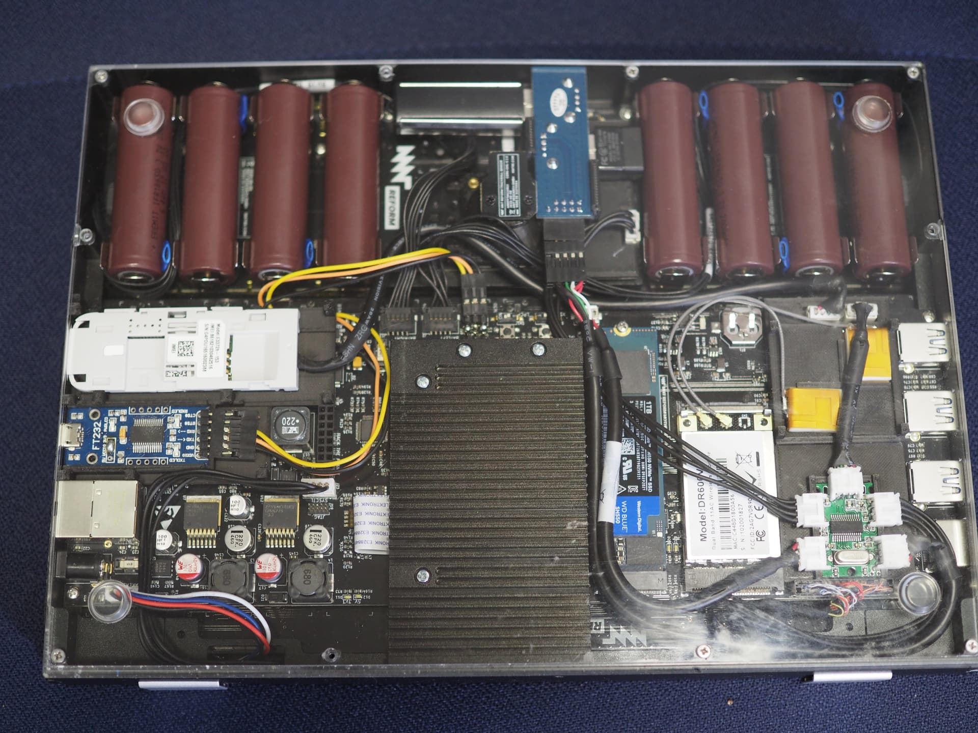
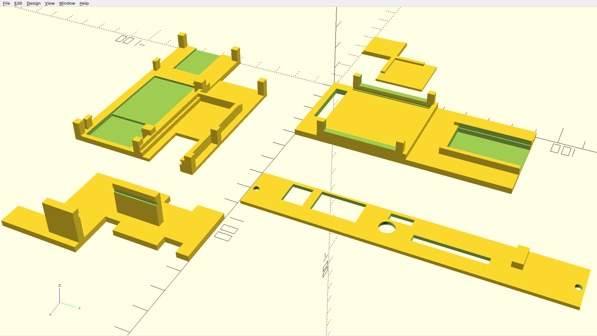
To neatly install all the additional hardware inside the reform case I got inspired by how the transparent acrylic antenna holder used the two JST PH USB connectors on the board to keep the acrylic rectangle in place and 3D printed a bunch of additional shapes using the same principle to stay in place without glue or tape or screws:
Top left: placed above the SD-Card slot and next to the Ethernet port. Includes clamps that fit a Huawei E3372 LTE USB stick after removing one of its plastic covers as well as rails into which a DEBO micro USB to UART adapter can be slid into. The little legs fix it in z-direction.
Top right: placed where the transparent acrylic piece would normally go using the same mechanism of using the JST PH connectors to remain in place. The small plastic piece can be slid into the bigger one and will hold a Laird antenna in place without needing to glue it (I don’t like the non-reversibility of glue). At the other end, a no-name 4 port USB hub from China (very popular on ebay) measuring 19 times 29 mm can be slid into.
Bottom right: alternative side-panel including an additional hole for the USB UART micro-USB port as well as a small plastic nob holding the top-left part into place in y-direction.
Bottom left: placed next to the trackball and holding a board with two USB-A ports into place
Shopping list:
A Huawei E3372 LTE USB stick – I chose that one because it seems to be very popular and easily available (also second-hand) and because after removing the USB housing it becomes slim enough to fit into the Reform
This USB UART adapter: https://www.reichelt.de/-p266053.html Having the adapter permanently installed into my Reform means I no longer need to take it apart or carry a USB UART adapter around with me just to access the uboot logs
Buy more JST PH 4 plugs, sockets and crimps because it’s easy to fail. The USB cables have to be soldered to the plugs in the following order: black (ground), green (D-), white (D+), red (+5V).
Originally I wanted to use the Nano Hub as a very tiny USB hub but that sadly has been sold out for months. Instead, I went with a cheap no-name USB hub with a FE1.1s chip in it. There are plenty of those on ebay and I got scammed twice in an effort to get one of those. An alternative is to buy the Manhattan USB Micro Hub for 9 USD and remove its housing. The board inside is only a few Millimeters larger. The bigger downside is, that then you have to throw the case away (and I dislike throwing things away) and that the legs of the JST PH sockets have to be bent just a little to fit where the actual USB-A ports were soldered before.
I will update this post with any questions you might be having. Thanks!
Option had a GTM line with combo wlan/wwan cards (of which only one model also had a sim slot and is unobtanium), i had one in a X220T for a while and it worked as advertised. If replacement modules were available it’d be nice…
josch, I would be interested in hearing about your experience with the reliability of your cellular connection. I ask because the Librem 5 is basically using a USB cell modem as well, and the connectivity on it is REAL hit or miss.
The convergence mode on the L5 is really compelling but with the state of the modem there it is a deal breaker. I need stable data as a minimum.
Thanks for sharing with us your work on your Reform!!
The reason I ask is because the cellular performance is real hit or miss on the Librem 5 which is using the same SoC. By hit or miss, I mean that sometimes the modem will not connect, sometimes it will but no data will work. Sometimes it will just disconnect and restart. Sometimes it wont show up after booting or resuming from suspend.
These are the reasons I am asking about stability. I would be interested to know if the USB modem is working after coming back suspend, etc.
Then I’m afraid I cannot answer your question. In contrast to your Reform, suspend is extremely unreliable for me and thus I rarely ever suspend my machine. That’s why I cannot test how reliable my LTE is after resuming from suspend because my suspend is unreliable.
I put everything together using the components mentioned in my last post, with the addition of a kit for making cables with male and female Dupont pin terminals and a crimper. I used wire I’ve salvaged from other electronics and projects in the past. Everything seems to be working well. There were a few tricky bits, though, which I’ll list below:
The four headers along the edge of the USB hub need to be soldered some distance away from the board in order for the board to slide into its carrier.
The right angle header pins on my UART board needed to be soldered in with the plastic bits on top of the board in order to be low-profile enough to fit. I clipped off the pins on the back with my flush cutters and carefully trimmed away the plastic bits. It’s a pretty tight fit on this carrier board, so clip the pins on the back as close as possible. I had to add 0.3mm to the channel into which the PCB slides to make it fit.
You’ll have to remove the USB connector from the Huawei. I’d never successfully desoldered a USB connector before, but I watched a few videos and managed it this time! “Helping hands” were essential here. I clamped the USB connector with the “helping hands,” added a bunch of solder to all the pins, ran my soldering iron along the pins, and gently pulling on the PCB. Cleaned up the PCB with a manual solder pump, a desoldering braid, and some flux.
The clips on the Huawei carrier are fragile. Ended up printing the carrier four times and the clips broke each time. (Using carbon-fiber reinforced polycarbonate.) Might’ve been an issue with my printing material, might have been a problem with layer adhesion, but either way: I wound up just holding the pieces together with Kapton tape instead.
The fit around the Huawei and the UART is a little tight. There are some “line out” pins under the UART that push it away from the PCB a bit, and the Huawei is a bit thick for the space, so the acrylic now bows out by about a millimeter.
Having the Huawei plugged in and in modem mode during boot seems to have given it priority over the wifi card somehow. I’ll need to work out what the problem is and figure out how to deal with it “correctly,” but in the meantime running this command seems to work, despite showing an error: sudo usb_modeswitch -u 8 -v 12d1 -p 14dc
Putting the Huawei into modem mode in the first place is done with: sudo usb_modeswitch -J -v 12d1 -p 1f01
Double-check that the product flag has the right value with lsusb first. IIRC, the product number changed after I took it out of “storage mode.” You also might need to install the usb_modeswitch command with sudo apt install usb-modeswitch first.
I think that’s everything. I put the OpenSCAD code into a repository on Codeberg, added support for the UART I happened to have on hand, and hopefully made it easier for other people to add support for other UARTs as well. I also broke the code up into modules to make it easier to pick and choose which boards to print.
@josch, I’ve released this code under the CERN-OHL-S license, which is the same license the Reform itself has been released under. I recognize I don’t have the right to do this unilaterally, as this is based on your code. Please let me know if you’d rather use a different license or host the code elsewhere or anything.
Meanwhile, I managed to fry something on my motherboard while doing this mod (released the “magic smoke” from some component due to letting metal touch the board with the batteries in) and now my batteries won’t charge, so I’ll be debugging that next.
Edit: Looks like I may have only burned out the trace from LEFTBAT to RIGHTBAT. Soldered some solid-core wire over the top and everything seems to be working again.
Interesting… I did not need to do anything like that. Everything worked as expected out of the box. Weird…
I’m placing my own code in the public domain (which is technically not possible in Germany but just imagine an equivalent to that) so feel free to do whatever you like with my openscad files including not mentioning my name or anything. I just want to put my openscad code out there and I do not care about any attribution or anything. But thanks for asking!
Oh really? Did you use the same one that josch was using? I have an old plunk phone that I just use a hotspot modem. That has worked well enough, or just using my phone. But there is something cool about having the ability built into the Reform especially if you don’t have a smart phone.
Yeah, same one. The fact I had it already on hand was a big part of why I tried the mod in the first place, TBH. It is a cool mod for sure, but 4G connections out where I live seem to have gotten slower as everyone switches over to 5G, and I’m really never in a place where either wifi or wifi tethering aren’t an option, so it just ended up not being worth it for me. I kept the USB connector for the LTE modem, so I was at least able to mostly put it back together. (Can’t seem to get the case to snap back together now, but it otherwise works.)
I upgraded from imx8mq to a311d and as a result, my 3D printed parts would not fit anymore:
since wifi is now on the SoM, the laird antenna cables are not long enough anymore and the antenna has to be repositioned
since the antenna is now positioned where the SD-card slot is and since the heatsink is a bit larger, the umts modem and its 3d printed carrier boards will not fit anymore
since there is now a fuse next to the internal usb headers, the 3d printed antenna and usb hub holder cannot fit anymore
This sounds like a lot of downsides, but there are also upsides:
since the a311d includes bluetooth, no usb bluetooth adapter is needed anymore
since the SSD moved from the M.2 slot to the PCI slot and since the a311d includes wifi and pcie wifi card is needed, there is now a bit more space in the case
since no usb bluetooth adapter is needed, there is now space around the trackball to add two pocket reform speakers
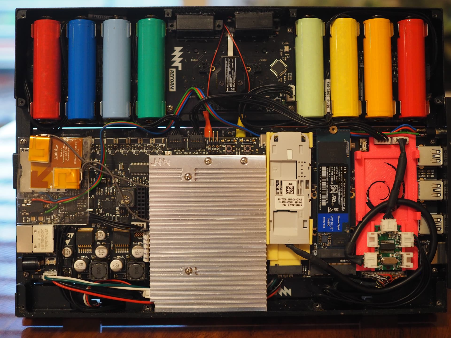
on the left there is the transparent acrylic that comes with the a311d and holds the laird wifi antenna
below that are three cables soldered to the headphone jack and that cable leads to…
the right-hand side where i have a second headphone jack next to the usb ports
in yellow PLA there is the new carrier for the UMTS modem which fits precisely between heatsink and SSD without any wiggle room. I created a 3D shape in openscad which fits into the M.2 connector and can be fixed to the motherboard with the usual screw on the opposite end
in pink PLA is the carrier board of the USB hub to which UMTS modem and keyboard are attached
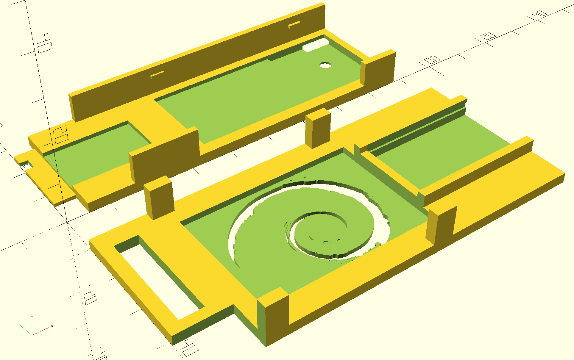
Here a screenshot of openscad with the two new 3D models you can see in the photo:
There is a Debian logo on the USB hub carrier because there was some free space that I could not come up with what else I should do with it. This also nicely fits the pink filament.