As I’ve been doing a number of board level repairs this year, I’ve decided to collect my notes here as they might help others to troubleshoot or to give to repair companies as a guide of where to look.
MNT Reform Repair (First EU Batch/R-2)
Date: 2021-06-30
Leftmost column of keys nonfunctional.
Probable cause: Short between power jack and keyboard switch.
Replaced keyboard with new keyboard (QWERTY). Kept old for refurbishing (MCU change).
i.MX8MQ SOM was damaged – no boot. Maybe only voltage regulators burned out. Stored for future repair.
Replaced i.MX8MQ SOM with new one.
Performed safety modification to prevent future problems: MNT Reform: First EU Batch? Do this safety modification
Tested all features with R2Test SD Card.
Cleaned up and put back into sleeve that it came in.
Repair Log: MNT Reform Beta (D-3)
Date: 2021-06-30
Cleaned keyboard and exchanged keycaps to MBK model (QWERTY).
Cleaned unit with compressed air.
Replaced missing screws.
Replaced all 8 battery cells (7/8 were dead).
Replaced discharge resistor R29 (it was exploded). 10 Ohms.
Performed charge control modification with a bodge wire (see MNT Reform R-2 Motherboard Update 2021-04-19).
Performed safety modification on power jack (see MNT Reform: First EU Batch? Do this safety modification).
Upgraded motherboard firmware to R2/20210419
Upgraded keyboard firmware to R1/20210419
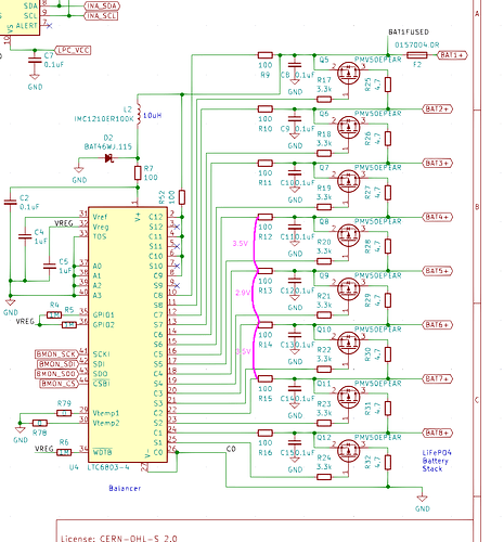
Had 2 bad measurements on LTC sense resistors:
Decided to desolder and exchange LTC6803-4 chip. This fixed the problem. The chip was faulty.
Performed charging test. Cell voltages nominal, charger correctly finished at top end.
MNT Reform Repair (R-3)
Date: 2022-10-26
Symptom: Internal display doesn’t work after a US repair company, PSI, originally fixed a problem with the power circuit. Then, they exchanged U10 with a new one (my suggestion). This did not fix the problem. Customer sent the board to us for inspection.
- The problem is that regulator U13 does not work. It supplies 1.2V for the eDP converter and the USB hub. The repair company did not check for/find this problem.
- U13 outputs only 0.025V
- LPCs 1V2_PWR_EN line is low, so it doesn’t enable U13 or U13 pulls the line low very hard
- U13 is the culprit. I removed the 0R on its enable and it is now high on the LPC side.
- Replacing U13 fixed the display (and i guess USB).
- I have also tested both pcie slots, ethernet, audio, battery charging and discharging. Looks all good.
MNT Reform Repair (R-3)
Date: 2022-08-03
Symptom: Internal display stopped working. In dmesg it looks like eDP link failed.
- The problem was a faulty U10 (SN65DSI86IPAPQ1). This is rare. Maybe the eDP connector was reversed or there was a static discharge.
- Swapping U10 with a new one fixed the problem.
MNT Reform Repair (R-3)
Date: 2022-08-04
Symptom: Motherboard burns a lot of power and generates heat immediately when on wall power.
- It turns out Diode D5 was shot. This causes some of the buck/boost MOSFETs to get very hot.
- Removing D5 fixes the problem. According to LTC4020 manual, this diode is optional, so leaving it off.
Motherboard repair on 2022-11-03
This one was complicated, took at least 4 hours.
Symptom: system uses 12W of wall power when powered off (no CPU module inserted). Q17 gets very hot, turns some sprinkled IPA into steam. owner already removed D5, a usual culprit, but it did not fix the issue.
initial repair:
- swapped Q17
- swapped U2
- swapped Q2
- removed D7, D6, D4. short is gone, but LTC (U2) not operational
- put D6, D4 back in → short is back
- measured 2ohms across Q2, that’s bad
- inducing power at 30V_GATE works fine, LPC is functional
- so the problem is close to buck/boost of LTC
- inducing 12V at BAT1FUSED also works fine, LPC detected on USB
- so the problem is close to the input stage of LTC
- candidates: Q15, Q1
- 120 ohms to gnd on gate of Q17. unlike on reference board
- replaced Q17 again. it was shot again! problem is gone.
- put in new D7. still fine.
- repaired HDMI connector with dental tools.
- replaced partially melted connector J23.
tests:
- SD Card boot OK
- eDP display OK
- HDMI OK
- PCIe 1+2 OK
- Ethernet OK
- RTC OK
- UART 1 OK
- USB OK
- SYSCTL OK
battery tests:
- highest cell (BAT1->2) measures 0. drop of 3V on F1.
- fuse F1 is shot!
- replaced with new fuse.
- now another cell measures 0. R14 measures 6V, R15 measures 6.5V, which is odd.
- this is fine, it was just the protected BB closing off one cell. opens after applying charge.
- cells are charging normally.
- LPC FW updated to latest version.
- repair concluded.
