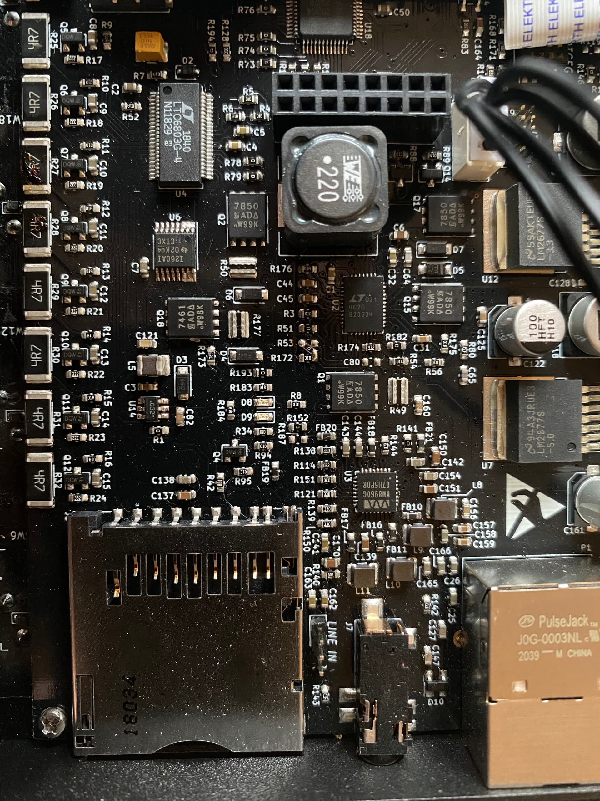
If you look carefully, R53 is now merged with R172
Today I used an AC adapter that outputs 19V, 6.3A as I forgot mine at the office. I checked the manual before doing so, 9-30V should be fine right? Another thing I did is a full apt update/upgrade
How should I proceed? Tomorrow I’ll move the resistor to its slot, is there anything else I should check before attempting a boot again?
Hey, sorry that you encountered this problem. How exactly did you test D5? In the diode failure case, continuity is there, i think in both directions. Do you have a diode tester in your multimeter?
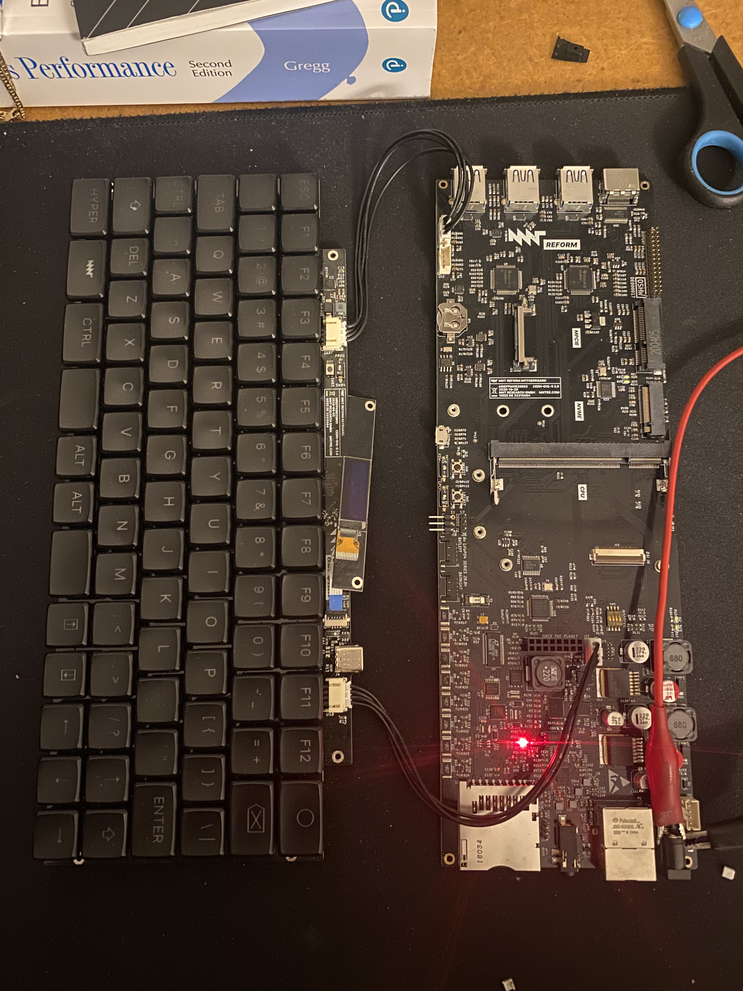
@minute So today (after 1 month) I finally received the fuses from lcsc so I replaced F2. I previously de-soldered D5 successfully thanks to your advices. The system booted fine (yeah) on battieries but as soon as I plugged the power jack in (with the stock reform charger this time) the system shut down and now:
when powered from batteries the system controller is responding but the system is no longer booting. No signals even from UART
when powered from wall power (batteries unplugged): no responses. LED D8 turns on
when both wall power and batteries are plugged the behavior is the same as the batteries were unplugged – no responses
It sounds like there is more damage to the motherboard related to the charger circuit. I would suggest not connecting the wall power at this point. How is the health of the batteries? Are they still at nominal voltages?
I would suggest to remove the i.MX module and the batteries, and first check the status of the motherboard/keyboard combo in isolation. The goal is to see if all the correct voltages are generated in the turned on state and the standby state (in standby, only the LPC_VCC 3.3V standby voltage should be there, and of course everything related to power input.)
Do you have a lab power supply? That way you can limit current and make sure it won’t create magic smoke if there is a short.
If and only if you have a controlled (current limited) power input, I would measure on the motherboard with a multimeter:
LPC_VCC (for example across C50): should be 3.3V in any state
Once turned on,
LEDs D12 and D11 should be on, indicating power on 3V and 5V rails
3V3 rail voltage should be 3.3V (for example across C167, near display connector)
1.8V should be 1.8V (across C112, southesat of C167)
1.2V should be 1.2V (across C37, northeast of coin cell holder BT1)
1.5V across C34 (east of C37)
5V across C33 (south of C34)
If you don’t have a controlled power supply, you can check the above rails for shorts. Before doing that, disconnect everything from the motherboard. Then, use the multimeters beeper function across the capacitors mentioned above. If something beeps, that’s bad.
If you don’t find a problem/short, I would suggest you send us the board for repair. You can contact support@mntre.com to get that going.
Ready to debug @minute So apparently there is already a problem with LPC_VCC, as D8 is the only diode lighting up and I’m not measuring any voltage across C50!