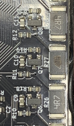
I had fried R28 when removing a battery cell while the power supply was still connected. I’ve replaced the resistor. The BOM describes the part as TE Connectivity 35224R7JT. Any 4.7 Ohm 3W resistor in 2512 (imperial) format should do.
My fried resistor still measured 4.7 Ohm, fwiw.
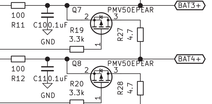
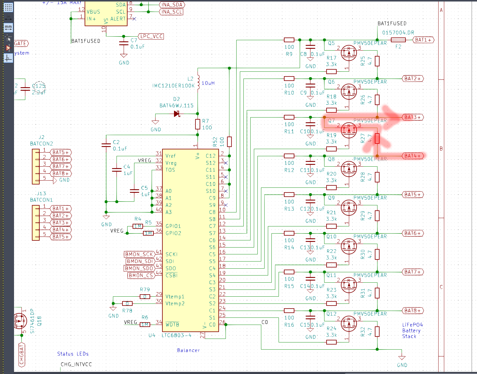
These resistors are used to balance cell voltages by discharging single cells through the resistor if the voltage of one cell is higher then the voltage of others.
It’s difficult to tell from the picture, but R28 also has some discoloration below the ‘4’ and might have been affected.
Did the components get damaged after connecting the power adaptor? Were all cells inserted when the damaged happened or were some cells removed (like in my case)?
Let’s attempt to reason over what might happen:
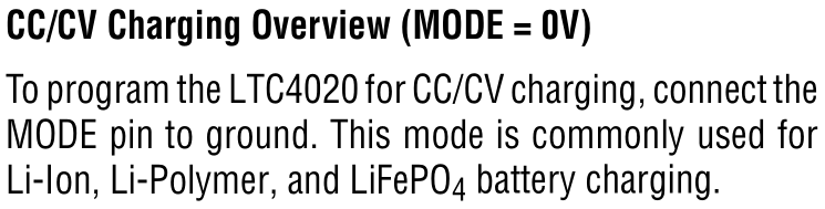
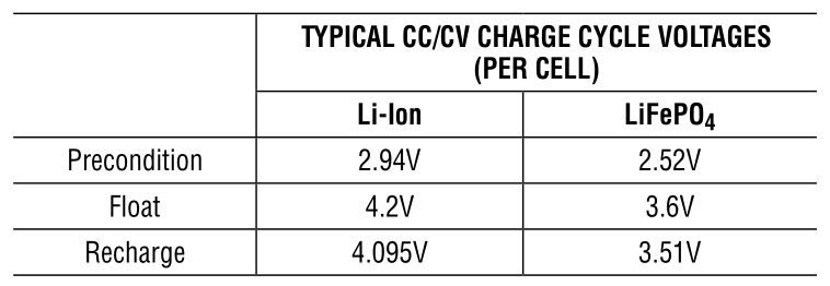
If we connect a 4.7 Ohm resistor directly to a fully charged LiFePO4 battery (assuming 3.6V), we should get 3.6 V / 4.7 Ohm = 0.77 A discharge current. That’s 3.6V * 0.77A = 2.77W and the 3W resistor should be fine.
I’m assuming that we can model charging batteries as a number of resistors connected in series. This is wrong, but might explain the principle. So if we’re charging 8x cells and want to reach 3.6V for each cell, we’re using 28.8V charging voltage. If each cell has the same resistance of 0.4mOhm, then each cell has the same voltage.
In a series resistor circuit all items have the same current which should be 28.8V / (8 * 0.4 mOhm) = 9000A. This is also the point where I’m certain that batteries can’t be modeled as resistors. I don’t use a 260kW power supply for charging. 
Now let’s assume one cell has gone bad and has a higher resistance than others. Let’s say one cell has 1 mOhm resistance (value made up).
Current changes: 28.8V / 3.8 mOhm = 7579A.
That would lead to 7579A * 0.4 mOhm = 3.03 V over 7 resistors each and 7579A * 1 mOhm = 7.6 V over the higher value resistor.
This higher voltage would trigger the balancing circuit and the system would try to discharge through the 4.7 Ohm resistor. I guess the single 1mOhm resistor would turn into a parallel resistor (1 / (1/1mOhm + 1/4.7Ohm) = 0.99 mOhm) in relation to the series circuit. The resistance value is close enough that I’m assuming the voltage doesn’t change.
So we’re sending 7.6V through our 4.7 Ohm resistor resulting in 1.6A (7.6V / 4.7 Ohm) and 12W (1.6A * 7.6V) which is too much for our 3W resistor.
I need to stress again that any calculation modelling a battery cell as a resistor is bogus (we certainly don’t see thousands of Ampere!), but I assume something similar is happening.
My goal was to calculate current to determine whether it’s likely the transistor got damaged. The transistor has a maximum current rating of 4.2A which would correspond to 19.7V through the resistor (4.7Ohm * 4.2A).
I believe power dissipation is calculated using the on-state resistance. There, we see max ~70mOhm specified. With this value we’d get ~30mV drop at the transistor (4.2A * 70mOhm) and 126mW (30mV * 4.2A) power dissipation which is well below the specified 480mW for the transistor.
Unless we get an excessively high voltage (>20V) through the discharge resistor and thus through the transistor, I don’t think the transistor got damaged. Given the time it took for magic smoke to escape in my case (multiple seconds), I’m pretty sure there wasn’t >80W (19.7V * 4.2A) flowing through the resistor. That’s ignoring that the PSU is 60W in the first place.
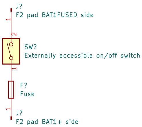
FWIW, just disconnecting the battery boards when not using them for a while also works, but is far more annoying than a manual switch or automatic disconnect on over-discharge.