The chip on the uart adapter is very sensitive. Just by holding mine in my hand (not touching any contacts) I get this output:
����f#�b��sgf3~D"�b���p������~����wwff?�"��������wgw�3D�xx���|D��f?�f3��3f~��3fw�s��������"D"�D3D3�f3f3�3ff��sfw�sw���������?�����������www�3f3��D��"D�D"D��D3f��f3f3f���������������������������������wfw�3D#���"D"D3D3�f3f3�3fw��sw��w�����������~|||����������������wgw�3F3D�"@#D3D��f3f3�s�������~||x�������������3f3��D�"D"D3f3�sw��p�������p�ww��f3f3D"��"f3>��s�����wwww�3f3D#�"D3f3f��w�������������f?�f�b�D"�D"`3D3f3�������www�3f3��D��"D�f3f��sw���������"D3f3ff�������ww�f3ff>��#D#�D�D>�D�����������������������������~F�D�F�D"�D3>��3f��s�����D�"D"f3f3����w�3gw?�f3f3f3ffD��f3f3D""D"`3F3f�9f3w�����www��F#��f�F��D������D"�D3f3��ff���p`ggf��D" @#D3f��f3f��s�����>D>�D�D#�f3�3w���p����f��F3�"D"D3f3f�`gff3�D�������p�p��"D�F3f3�sf�������`ww�f3D�"D"`3D3f��f3f�pwwf�D"��������p������p���������3D��f��D>����~���������������p����sgf�D"�"D"D3f3�sfw�s���7�D>������p�������pw�f�D#�>�D�D?�f3��s7@"�D3��f3f��s�����p���~|�x��D�D��f?�ff������9��www��D�"D�F3f��fw�����F�D��wf3f3|Dx|||���~�f?�f�������fx��D>�D?�f��f?�fw����p�p���f?�F���"D3��f3f��s�����wwg�D""@"D��f3��3f���w����wff��D��wwF3DD������p����g~�f���f3F3���3ff�F#D <�F�D��D�D�1f�fg?����������������������~~~����pwww�wf��`www��3f3��D"��������~|||��"D3f���f�f�D�����������������������������f�ff�f3D3��D"�D#D��f3f��s��D�`��f?�F��|���"@#D3f��f3f��sw���������"D"D3���ww���3f3��"D�"D>�D"f3��f3f��sw�����������3ff��3D#�D��D>�D��F?�f3��3w��s������p��ww��3f3��F3D"D�����pww���3f3��D"�"D�D3f3�f3w�s������p�����f?�f��D���������������������������w�������"@#D3F��f3f��sw��f3ff?��#D"�"f3f3������`����3fw�f3D3D"�w���1�|~��wf3D����sf>D0����f��f�F�D">��8gf3D��~��pwwg�D"�"D31f3f��s������~||����D�����������|������>�F�D�D"@#D�1f3������g�"D"f3f��s����p������|�"D3��f3�������3f3�D�������f?�f�"�D"�f3f��s�����ww���3f3��D���>�������������www�f3f3D#xww��3f3�D���3f3��D����|��������������������������������������f���������?�>�>�>>|��||||<>>�>�>�~��������>�>�>><|x�#f3�fw����fwg?�f3F#|D�"D3f3f������3f3>D"�f������������p���f�~f�D"|�D"D3f3f�g�����"f3��fg����������p������~�~�~~��D�D�D"D3��f3f�����D>��������������x��ww���3ww�3f3�D#D"D"������p������~�~~~��D����"D3��fw�����ww��3ff�f3D�D"xx||����3>����www��3f3��f3D"D�""`3f3f?�����g�?�f��||x�����f?�����||x��"D3f3f���p�����~�~�~��|D�D@����?��������������||x��www��3f3~F3D#|D">�D�D3�f��w��������ww��3f3��F3D"D"��w�?�����||xD""`3f3f��fw���1�>��>����"D"f3f��s��p��ww��3f3��F3D�D"1�?����������������������|�D"<�3f�ffw�������������~����~D�F�D"��"�f3�������www�3f3~F3D#|D"�p������~�~�~~~||||x�f�f�F�����www��3ff��f3D�D"�"f3>��s������ww��3f3>�D#D"D"|||||������"D3��f�����������~�~�~��D�D����3gf?��3f3�D"�"D"f3f��x��3gg?��3f3�D"x|||||~~�~�������������~�~��D�D��"f3��f�����wwwwfFD"D3>��3f�����ww�3f3��f3D"D"�>��>��������������������~�~�~~��D�"�"D�f3����|||||~~��������"D3�f3����"D39f3w��D�D�D"D�f3f3����p����~�~~~|�����ww��3ff>��3F3�D"x|���~������p���3gg�3f3~D"D||||~~�~�~�������w���w�f3f��f3D�D"�"
Now that I have tinkered with my own Pocket Reform for a bit more I have a few ideas. Firstly, about UART:
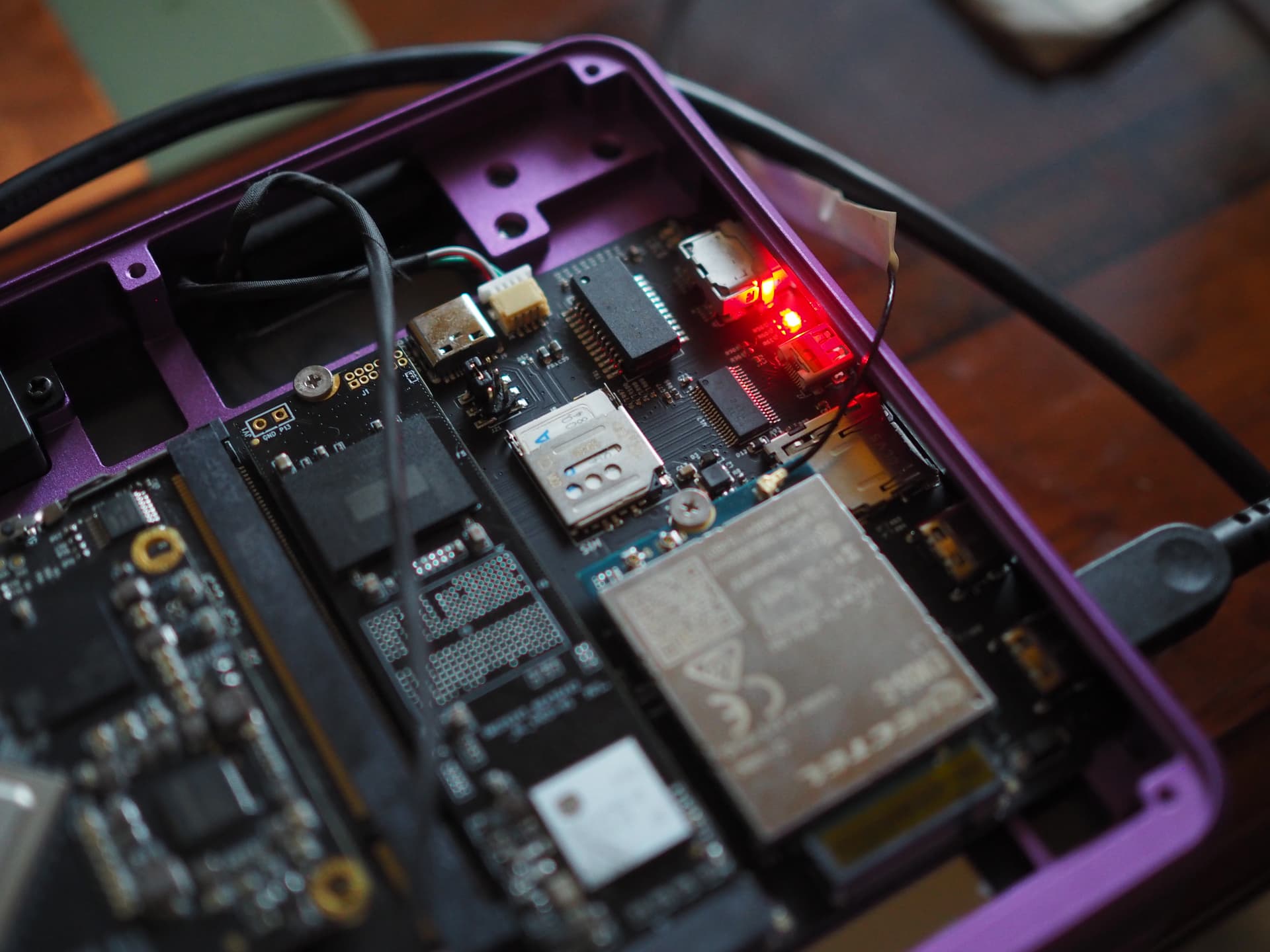
Make sure, that you plug the TX cable of your adapter to the RX connection on the board and vice versa. I noticed that the Pocket Reform DIY Assembly Manual only contains photos for the i.MX 8M Plus, so here is a top-down view of how it (nearly) should look like for your rk3588:

I left my own uart adapter plugged in that photo so that you can see which of RX, TX, GND goes where. I said “nearly” above because you’ll see that at the bottom, where the 7 pin connector J1 is, I have both cables disconnected. This is because my charging board is broken. But maybe this is something you should try out as well to reduce the amount of error sources. Disconnect the two cables and bridge pins 2-3 with one of the jumpers as I explained here with more photos: Running the Pocket without batteries (bypassing a broken charging board) Doing that will help make sure that the batteries or the charging board are not responsible for the problem you have.
After you have made this modification, you can power up your Pocket Reform just by having it plugged into USB-C. Once you plug it in, even before powering it on, a red LED will light up:
Do you have that as well? If not, make sure that the Standby Power Switch is in the correct position away from the hinges. I took another photo from a different perspective. Maybe it helps you spot what what else could be missing in your setup:

I think it’s a good idea to take the charging board and batteries out of the picture by bridging pins 2 and 3 of J1. This will allow you to power the motherboard with the rk3588 standalone without having to worry about any problems with the battery board or the batteries. If everything works and if you have your uart adapter plugged in properly then you should be seeing this in tio (I see you are already running it with the correct baudrate):
ch0 ttot10
ch0 ttot10
ch1 ttot10
ch2 ttot10
ch3 ttot10
ch0 ttot18
LPDDR4, 2112MHz
channel[0] BW=16 Col=10 Bk=8 CS0 Row=17 CS1 Row=17 CS=2 Die BW=16 Size=4096MB
ch1 ttot18
channel[1] BW=16 Col=10 Bk=8 CS0 Row=17 CS1 Row=17 CS=2 Die BW=16 Size=4096MB
ch2 ttot16
channel[2] BW=16 Col=10 Bk=8 CS0 Row=17 CS1 Row=17 CS=2 Die BW=16 Size=4096MB
ch3 ttot16
channel[3] BW=16 Col=10 Bk=8 CS0 Row=17 CS1 Row=17 CS=2 Die BW=16 Size=4096MB
Manufacturer ID:0xff
DQS rds:h1,h1
CH0 RX Vref:32.6%, TX Vref:13.2%,13.2%
DQ rds:h1 l0 l0 h1 h1 h3 h2 h6, h1 l0 l1 h1 h1 l0 h3 l0

DQS rds:h1,h1
CH1 RX Vref:34.4%, TX Vref:13.2%,13.2%
DQ rds:h2 h1 h1 h2 h1 h3 h1 h5, h3 h3 h7 h2 h2 h1 h3 h1

DQS rds:l0,h1
CH2 RX Vref:36.9%, TX Vref:13.2%,13.2%
DQ rds:h3 h4 h6 h6 h1 h5 h5 h7, h2 h3 h4 h2 h1 h4 h6 h5

DQS rds:l0,h1
CH3 RX Vref:38.1%, TX Vref:13.2%,13.2%
DQ rds:h4 h6 h2 h1 h1 h2 h2 h3, h1 h4 h2 h3 h4 h4 h3 h2

stride=0x2, ddr_config=0x4
hash ch_mask0-1 0x20 0x40, bank_mask0-3 0xa00 0x1400 0x2800 0x0, rank_mask0 0x401000
change to F1: 528MHz
ch0 ttot10
ch1 ttot10
ch2 ttot10
ch3 ttot10
change to F2: 1068MHz
ch0 ttot12
ch1 ttot12
ch2 ttot12
ch3 ttot12
change to F3: 1560MHz
ch0 ttot14
ch1 ttot14
ch2 ttot14
ch3 ttot14
change to F0: 2112MHz
ch0 ttot18
ch1 ttot18
ch2 ttot16
ch3 ttot16
out

U-Boot SPL 2024.10-g424c714eb247-dirty (May 06 2025 - 15:46:29 +0000)
Trying to boot from MMC1
NOTICE:  BL31: v2.12.0(release):v2.12
NOTICE:  BL31: Built : 15:46:29, May  6 2025


U-Boot 2024.10-g424c714eb247-dirty (May 06 2025 - 15:46:29 +0000)

Model: MNT Pocket Reform with RCORE RK3588 Module
DRAM:  16 GiB
Core:  327 devices, 26 uclasses, devicetree: separate
MMC:   mmc@fe2c0000: 1, mmc@fe2e0000: 0
Loading Environment from nowhere... OK
In:    serial@feb50000
Out:   serial@feb50000
Err:   serial@feb50000
Model: MNT Pocket Reform with RCORE RK3588 Module
[mnt-reform-series-rk3588] setup_usb()
Hit any key to stop autoboot:  0
Scanning for bootflows in all bootdevs
Seq  Method       State   Uclass    Part  Name                      Filename
---  -----------  ------  --------  ----  ------------------------  ----------------
Scanning global bootmeth 'efi_mgr':
Card did not respond to voltage select! : -110
No EFI system partition
No EFI system partition
Failed to persist EFI variables
No EFI system partition
Failed to persist EFI variables
No EFI system partition
Failed to persist EFI variables
  0  efi_mgr      ready   (none)       0  <NULL>
** Booting bootflow '<NULL>' with efi_mgr
Loading Boot0000 'mmc 0' failed
EFI boot manager: Cannot load any image
Boot failed (err=-14)
Scanning bootdev 'mmc@fe2c0000.bootdev':
Card did not respond to voltage select! : -110
Scanning bootdev 'mmc@fe2e0000.bootdev':
  1  extlinux     ready   mmc          1  mmc@fe2e0000.bootdev.part /extlinux/extlinux.conf
** Booting bootflow 'mmc@fe2e0000.bootdev.part_1' with extlinux
U-Boot menu
1:	Debian GNU/Linux 13 (trixie) 6.14.6-mnt-reform-arm64
2:	Debian GNU/Linux 13 (trixie) 6.14.6-mnt-reform-arm64 (rescue target)
3:	Debian GNU/Linux 13 (trixie) 6.12.27-mnt-reform-arm64
4:	Debian GNU/Linux 13 (trixie) 6.12.27-mnt-reform-arm64 (rescue target)
Enter choice: 1:	Debian GNU/Linux 13 (trixie) 6.14.6-mnt-reform-arm64
Retrieving file: /vmlinuz-6.14.6-mnt-reform-arm64
Retrieving file: /initrd.img-6.14.6-mnt-reform-arm64
append: ro no_console_suspend cryptomgr.notests loglevel=3 clk_ignore_unused cma=256M swiotlb=65535 fbcon=rotate:3 fbcon=font:TER16x32 console=tty1
Retrieving file: /dtb-6.14.6-mnt-reform-arm64
## Flattened Device Tree blob at 12000000
   Booting using the fdt blob at 0x12000000
Working FDT set to 12000000
   Loading Ramdisk to e9cd9000, end eceb2a4c ... OK
   Loading Device Tree to 00000000e9cbf000, end 00000000e9cd8cce ... OK
Working FDT set to e9cbf000

Starting kernel ...
Final note: taking the charging board and batteries out of the loop is just an idea to maybe debug this better. It is very likely that your charging board is completely fine because you say above that your keyboard is functional and the OLED is coming on. That would not happen were your charging board broken. I think debugging this via some uart output might be the best way forward, assuming that indeed your rk3588 is seated correctly but now you have some more photos to compare how it should look like. ![]()