when my charging board broke, minute provided immediate assistance to me on IRC to get my pocket back in action: 2025-05-22.log
Since there is no structured guide for this from MNT (yet) and since I just took these photos anyways, I wanted to share these steps with you in case they are useful for somebody. This expands on what @staticbunny already wrote in their post (also with photos) but uses one of the jumpers from the Pocket Reform motherboard as suggested by minute instead of a custom bridge. Another write-up on this topic was performed by @benedikt in their post here.
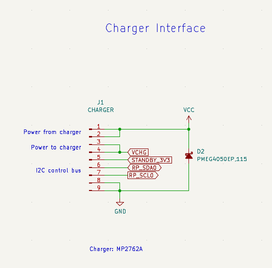
The idea is to bridge pins 2 and 3 of connector J1 as @Jonas had already written here. Here is a screenshot of the relevant part of the KiCAD schematics:
As @Jonas notes, the above can also be found on page 14 of the manual
According to minute, the recommended way to bypass the charger is to first unplug the two cables from the J1 9-pin connector and then borrow one of the extra 2 mm jumpers from the internal usb-header just next to the internal usb-c connector. That jumper is then placed on pins 2 and 3 (counted from the left) of J1, the 9-pin connector to which the charger board was connected:
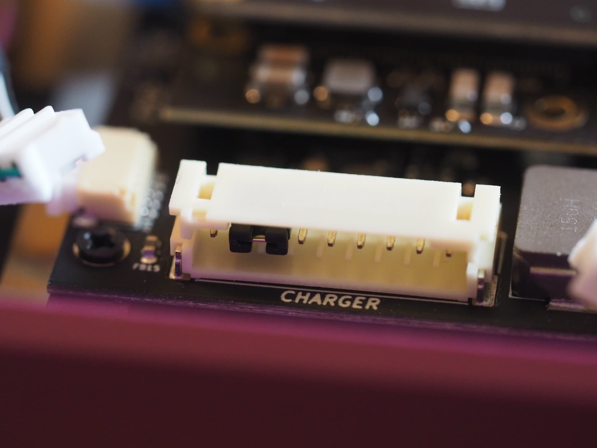
That way, as one can see in the schematics above, the “power to the charger” and “power from the charger” lines are bridged, essentially bypassing the charger completely. Here is a close-up:
With that modification performed, one can now operate the Pocket Reform from an external USB-C PD power source. I am carrying a power bank around with me until my replacement charger board arrives. That way, I’m still mobile with my Pocket Reform despite the broken charger board.
One other benefit to this while you wait is that you aren’t needlessly charging or using your batteries and thus saving their charge cycles for when you actually need them. Thanks for the nice write up!
Same same but different: can I run it from USB-C PD if I disconnect the batteries from the charger board (but leave the charger and motherboards connected)?
I have a working (as far as I know) Pocket/charger board. I plan to remove the batteries as described in this step and wonder if it’s safe to power on via USB-C PD before reinstalling them? Thanks!
No. You have to bridge pins 3 and 4 as explained in other threads to bypass the charger board. Just removing the cells from the charger board is not enough.
Thanks! The threads I found all concerned broken charger boards: just confirming, does this apply to working as well as broken ones? Does powering on via USB-C PD before reinstalling the batteries risk damaging the charger board or anything else? My goal is removing the batteries, not necessarily bypassing the charger board … checking: does powering on with a working charger board without batteries require bypassing it?
I’m just now closing up my pocket after bridging pins 2/3 on the charging inputs. Boots up just fine and I’ve got external batteries for days (glad to have my pocket back up and running again); Ordered some replacement batteries (just to rule that problem out) and upgrading to the 706090 - so, if they work as intended, I’m going to end up with larger capacity as well. But I might need to replace the charging board if the batteries don’t appear to be the issue. Will report back with my outcomes.
@josch Thanks for sharing this! I have a few questions:
Is this something related to charging board 1 vs 2? I am reading a lot of problems on the forum about power issues with the pocket, so just trying to understand as much as possible.
What happens if you flip the power switch to off instead of standby? Does it:
Just block all power
Just block the battery so you could still power it with a USB-C power bank?
Thanks!
Edit: My Organelle-M has never failed me as long as I have been providing it with either fresh batteries or an external power supply. Would be fantastic to have some sort of idiot proofing of Pocket Reform as well. Some solution that would just always work if you had access to a power outlet or power bank.
@dfbarth@lislegaard There is a bug with charging board v1. Lucie investigated the cause together with the manufacturer of the charging chip but was never able to get to the root cause of why it sometimes fails. If it did fail, it is sometimes visible to the naked eye that the chip broke. There are other topics here of people with photos of the broken charger chip (see my initial post). Compared to when I wrote my initial post, there is now a structured guide (with photos) which helps you diagnose the cause: MNT Support
Essentially: if your OLED stays blank and if bridging pins 2 and 3 fixes the problem and makes the unit work and if you have charger board v1, then you very likely have a broken charger board and you can get a replacement as part of your 2 year warranty from MNT.
It will disconnect the keyboard from the rest. The keyboard will send a short signal (i think it was “r1”) over serial to the systctl to switch on the pocket. To do that it is “always on” and will keep drawing a little bit of power from the batteries. Switching the standby switch off, disconnects the keyboard completely so you cannot switch it on anymore (unless you connect another serial device to send “r1”).
And no, even with usb-c power connected, switching the standby switch to “off” will switch off the whole device.
Well, I can report success - after changing to the v2 charging board, I … wait a sec. There was a problem. During the downtime/board failure, one of the lipo batteries died pretty hard. Once I reassembled everything, there wasn’t enough ‘go’ in the batteries to run the internal system so that I could charge the batteries back up. I’d recently sourced a jst charger - but the polarity was backwards on the charging ports (I DMM’d around and discovered one battery was showing negative voltages, and the other battery showed next to nothing) - so, I had to roll the pins (jumper wires into the correct polarity) and that got me charging. After about 30 minutes on the charger (I had an inline USB meter telling me the draw and as it started to drop off, I figured I was safe to migrate back to having the batteries installed)
tl;dr - once the batteries have enough charge, then the v2 charger board works as expected when installed.
Now I just need to figure out how to get apt to stop trying to remove ‘reform-desktop’ when I attempt to update or remove certain applications (like evolution)
I’m in the same boat: broken charging board and waiting for a replacement.
My question: Can I install and run the new 3588 V2 upgrade in my Pocket minus the charging board? Or should I wait for the new charging board to arrive before installing the CPU upgrade?