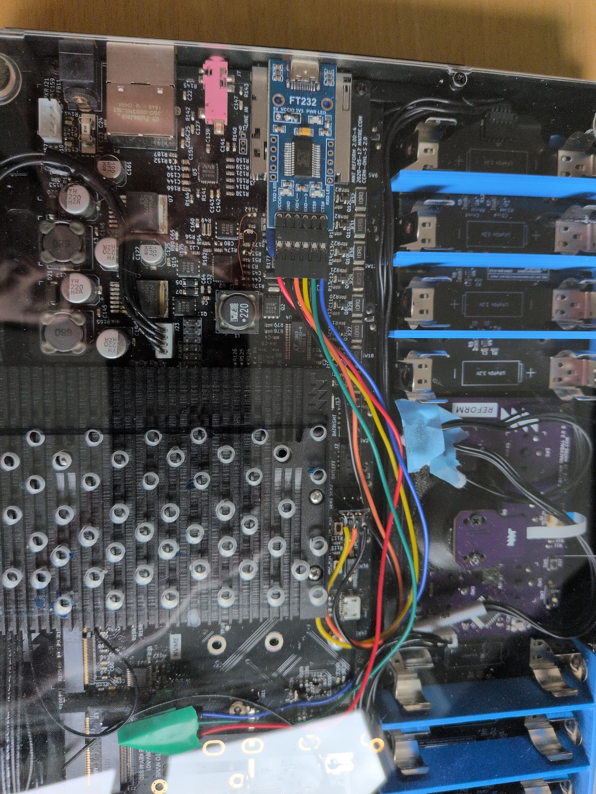
I’ve successfully used a 3-pin 3.3v UART/FTTDI USBA cable to observe my mnt reform with bpi-cm4’s boot process. It worked great!
But because of the position of S2 and the construction of the cable, I can’t really do this test without having the acrylic piece off, and this isn’t particularly conducive t day to day usage. Since the thing I want to debug appears to happen randomly, having a way to connect and have the cable outside without compromising other usage seems tricky.
It occurred to me, since there are only 3 wires involved, that a 3.5mm jack might allow me to run wires from the S2 connector on the motherboard to the side of the case, and then I could make an adapter from a 3.5mm male jack end to pins the UART cable could connect to.
It’s possible this won’t work due to resistance/impedance/whatever, but it also seems like a pretty doable option – my first idea was just to connect up the cable internally, take off one of the side plates, and have it hang out the side, but I don’t think there’s enough clearance between the S2 pins and the acrylic baseplate to do that, and this would be a lot cleaner, regardless.
Anybody know why this wouldn’t work? Or have a better idea?
Yup, this is likely going to work. I think I remember that users on IRC have already done the exact same thing. There is also enough space for a 3.5 mm audio jack on the right side-panel. I am using it for actual audio though:
Another popular solution is to include the usb uart adapter in the classic reform case and then connect to the now internal uart adapter via micro usb or usb-c. This used to be my setup 3 years ago:
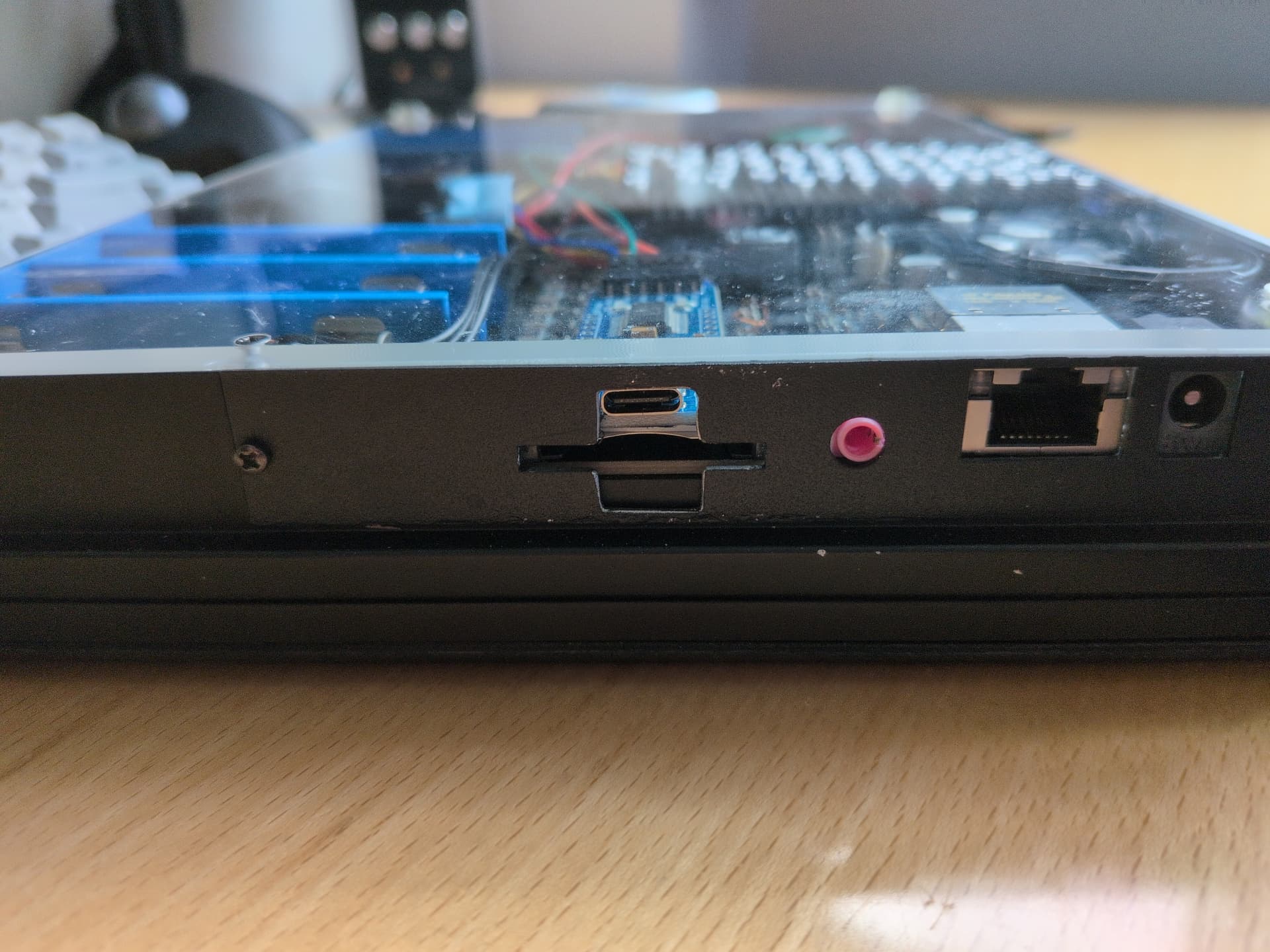
Same as @josch - I’ve installed a UART to USB-C adapter in one of my reforms. I taped it to the SD card slot using double sided tape and filed out space for the Type-C port in the metal side panel. As you can see, I was too lazy to double check which side to file, so I filed the wrong one first, of course m(
I guess I know what my next project will be! =) Thanks, all – gotta get some parts! Also, @vimja – I like the exhaust holes over the CPU card’s heatsink. Does it help?
I sure like to think so. But to be honest, I’ve never done serious before / after testing.
But when compiling, which I do a lot, I run Gentoo, I have a large 200mm Noctua fan blow air at the bottom of the device. So in that scenario at least, surely the holes must make some difference, actually allowing the air stream to reach the heat sink…?
Also, I’ve been wanting to install a FAN for a while. Even got myself a model that fits (mechanically): https://www.sepa-europe.com/product/hy60q05pse04bp/ but I haven’t found a way to control it yet. Currently waiting on motherboard 3.0 with the new I2C header.
Well, I got my parts, and today awkwardly drilled a hole in my USB/HDMI side panel for the panel-mount TRS jack, which fits and has lots of clearance and everything. Unfortunately, the leads I got don’t fit any better on S2 with the plexiglass on than the actual adapter does, so… I think I might have to just wire wrap (until my rk3588 board arrives).
Also, my attempt to solder leads onto the TRS jack itself was an irritating fail – it’s been a long time since I soldered anything, and my eyes aren’t what they once were. It’s clear I need some helping hands and a magnifier light, or something.