While having trouble with Upper left battery on OLED discharging faster - #3 by pcbnoob I found out that the upper left battery on the OLED corresponds to the right battery on the left battery module in contradiction to the handbook Input Devices — MNT Reform Operator Handbook documentation. Can someone verify this?
Mapping in the manual is wrong for the left battery module, for the right one it’s correct.
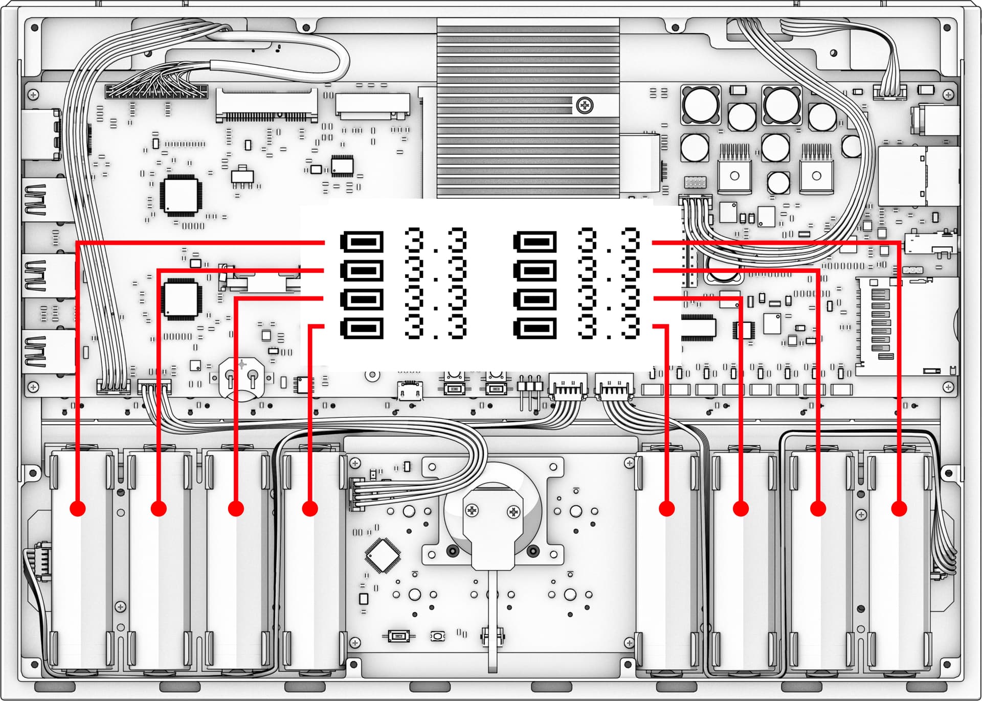
![]() The left module is turned 180° for mounting.
The left module is turned 180° for mounting.
The right module:
2 Likes
Yes ![]()
(with our machine and the last https://community.mnt.re/t/mnt-reform-r-2-motherboard-update-2021-04-19/177 LPC and Keyboard update. )
I’m impressed that you managed to do all the battery swapping without shortening anything. I think I destroyed one of my cells by accidentally having two of the contacts touch when I did some similar experiments. Maybe you are interested in one of the insulation tips from this thread: Isolating battery clips
If it turns out that you also ended up permanently damaging one of your cell, don’t hesitate to ask me for one of mine: JGNE 18650 1800mAh original MNT Reform battery giveaway
I created this issue for the handbook to not loose track of this: documentation of old battery mapping is wrong (#3) · Issues · Reform / reform-handbook · GitLab
2 Likes
![]() First time I removed all batteries I didn’t know about the problem. I think 80% luck and 20% precaution removing the BATLEFT & BATRIGHT connectors. After reading some posts and knowing the problem, while still removing the BATLEFT & BATRIGHT connectors I took them out with more care
First time I removed all batteries I didn’t know about the problem. I think 80% luck and 20% precaution removing the BATLEFT & BATRIGHT connectors. After reading some posts and knowing the problem, while still removing the BATLEFT & BATRIGHT connectors I took them out with more care ![]() . Isolating the contacts with heat-shrink is the best solution (the 3D printed separator is nice but not as effective) because if the blue isolator/heat-shrink of the LiFePO is rubbed off there will be a short on the positive end of the battery (the battery casing is the negative pole). I think that happened here https://community.mnt.re/t/battery-failure/604
. Isolating the contacts with heat-shrink is the best solution (the 3D printed separator is nice but not as effective) because if the blue isolator/heat-shrink of the LiFePO is rubbed off there will be a short on the positive end of the battery (the battery casing is the negative pole). I think that happened here https://community.mnt.re/t/battery-failure/604 ![]()
The battery was discharged because the balancing resistor was always on while charging https://community.mnt.re/t/upper-left-battery-on-oled-discharging-faster/1071. I think the balancing process will take long time with such a difference in Voltage. I’ll try charging the cell with an external circuit. If the cell is dead I will ask you for the giveaway - Thank you ![]()
![]() .
.
Please let me know if this is the wrong forum - I am new but I’m trying to contribute. I also searched before reaching here and this was the closest to my current question.
- In the schematic for the motherboard which shows the LT6803-4 “Multicell Battery Stack Monitor”. It shows one side of the chip with C0, {S1,C1, … S12,C12}. However the chip’s datasheet shows C2, {S2,S3, … S12,C12}, V* which does not map 1:1 with the schematic.
Question: Which is correct?
- I want to create a cutoff hard switch for the battery pack(s). Given there are 8 leads for BATT 1-8 and one for ‘Ground’ (handbook), ‘V-’ (datasheet it appears to me switching that 9th lead would accomplish the goal.
HOWEVER, I’m at a loss from the schematic as to how BATT1-4 get the V- (or ‘Ground’) to join the V-/GND on BATT5-8 which is on pin 5 of J2 (BATCON2).
Q: How does GND from BATT1-4 connect up to GND from BATT5-8 to go to J2 (BATTCON2) pin 5?
- In the schematic J13 (BATCON1) pin 5 indicates it’s also connected to BATT5, which really is connected on J2 (BATTCON2) pin 1. On physical inspection of the hardware I’m not seeing how it could be. Like my question of "how do the grounds meet between BATT1-4 and BATT5-8 I wonder how the heck BATT5 could cross over to J13.
Q: Is this another problem with the schematic or is there another connection somewhere I’m missing?
Big thank you to all the posters who helped steer me to markup and assisted in showing me where I could learn more about it!
Ehud Gavron
Tucson, Arizona, US
Hi gavron.
To 1. : The order of the pins on the rectangle for the LTC6803-4 in the motherboard schematic is different from the order in the datasheet. On page 2 of the datasheet there is a pin mapping which shows the pin numbers and their functions like you where looking to the top of the chip (check page 38 too). The order in the schematic is different but the pin numbers map to the right functions.
To 2. : read → Battery is not charging - #25 by johkra
To 2/3. : The batteries are in series. Bat. 1-4 and Bat. 5-8 are bridged on the corresponding battery holder PCB / the two battery holder are bridged via the connectors J2 and J13 by a trace on the PCB (you can check it on the PCB exlorer: Interactive BOM for KiCAD
which is linked here: https://mntre.com/reform2-handbook/system.html. There is no common GND for all batteries. Bat. 1-8 and GND connections are to balance the batteries and measure the voltages and of course Bat 1. and GND are used to power the mainboard and to charge the batteries ![]()
1 Like
Thanks, pcnoob, you just saved me a whole lot of time and some dead ends. I’ve read the first few pages of the johkra thread you linked to. Ouch. Time to go back to the schematics (the ones that are right) and focus on where a shunt can be put in. Between two MOSFETs, Zener diodes, 25-30VDC all I can say is “ouch” again.
E
I saw that MNT Reform Battery Board (protected) - MNT Research Shop was added to the store which promises to add all relevant protection features. It’s not currently in stock, though.
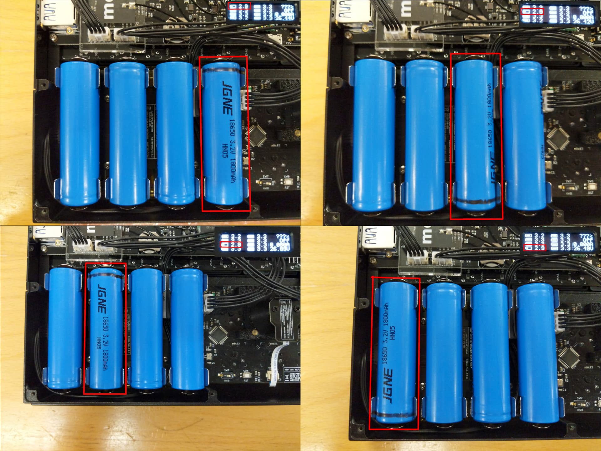
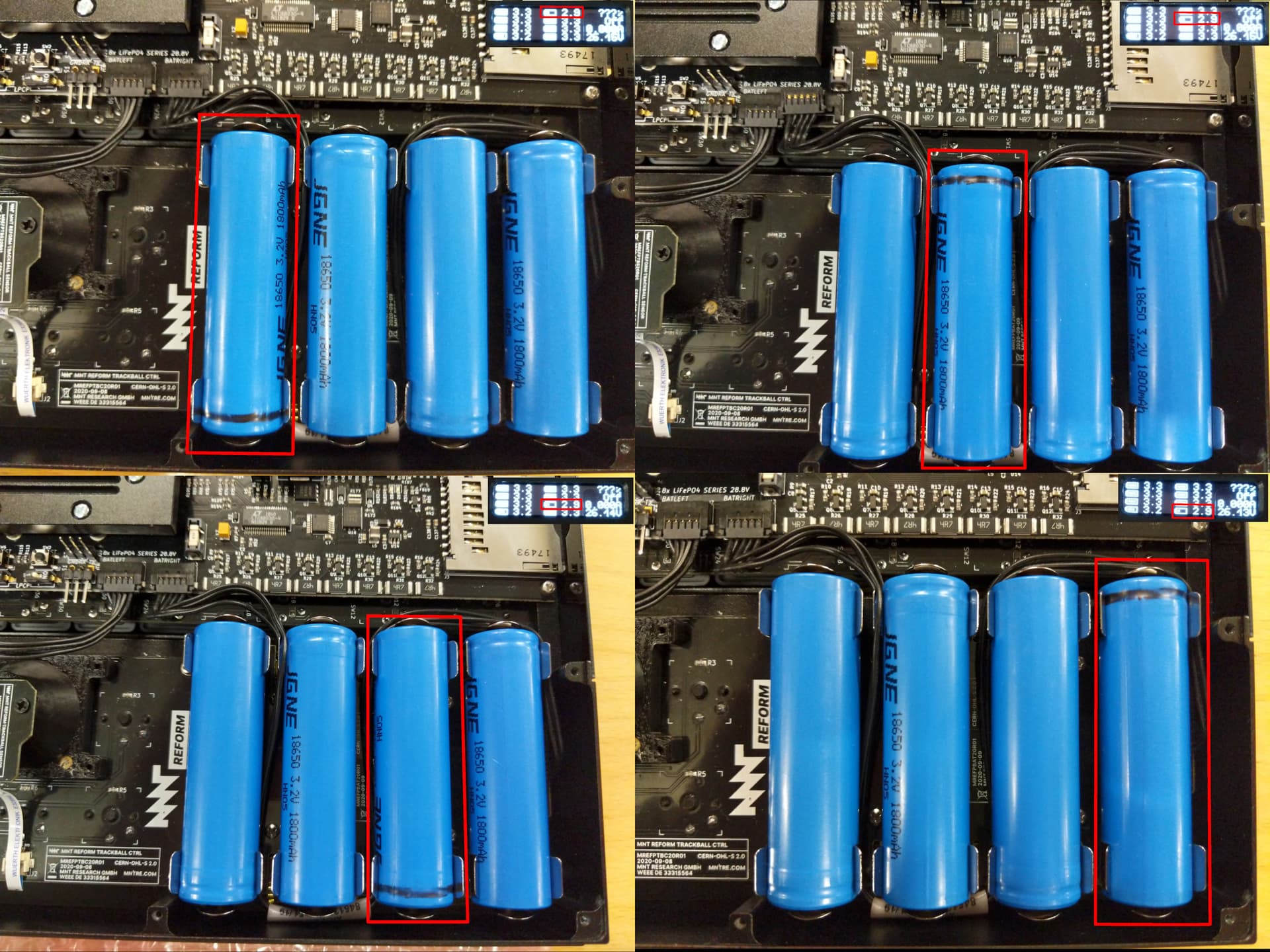
The image I posted above is not always correct it turns out.
I just tried removing the fourth cell from the left in the image. The result was, that the bottom left cell in the display was shown as missing.
I updated my lpc firmware a few weeks ago. Maybe the lpc firmware upgrade changed how the cells are reported?
Okay, so I just changed two of my cells and used the opportunity to investigate a bit further. With the latest firmware version 2023-07-03 from here:
Those are the current mappings:
I have no idea when this changed in the lpc firmware but it seems the handbook is correct after all if the lpc firmware is new enough.
1 Like
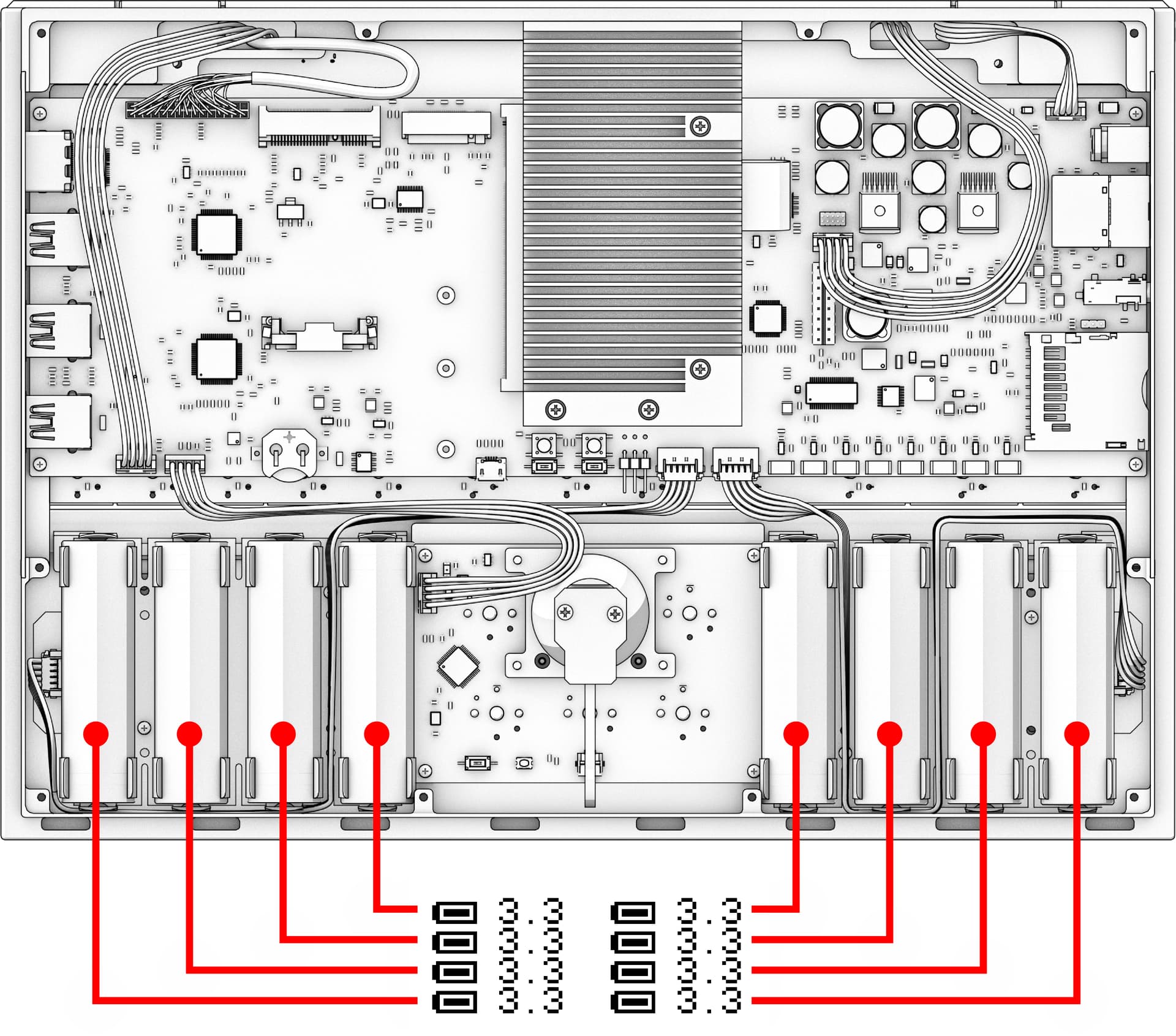
Hi, we just discovered that the old unprotected and the new protected battery boards have the cells connected to the motherboard in opposite order.
There will be a section explaining how the OLED battery monitor corresponds to the actual cell position in the new handbook.
1 Like